ASME UG-99 Hydrostatic Test Stress Calculations
ASME Code paragraph UG-99 requires that all vessels undergo hydrostatic (or pneumatic) testing before Code stamping. As this test provides mechanical stress relief it may be thought of as the final step in the fabrication process. The UG-99 hydrostatic test is an effective way to screen for design, material and fabrication deficiencies as well as to prove the structural integrity of the equipment.
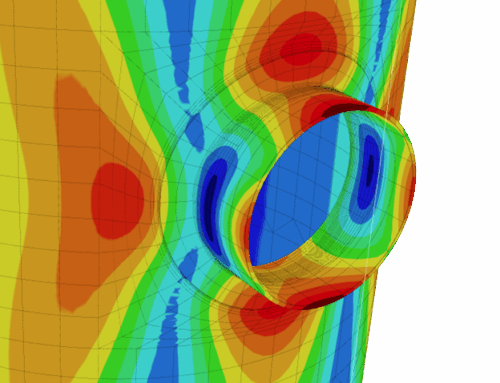
However, this raises the question – what constitutes a hydrostatic test “design deficiency”? Although ASME Section VIII-1 does not prescribe a test stress limit, vessels that undergo “objectionable distortion” during testing may be rejected by your AI. COMPRESS and INSPECT include a Hydrostatic Test Stress Calculation Feature that assists you by:
How do I view the Hydrostatic Test Report?The Hydrotest Report is available to all COMPRESS and INSPECT users. To prepare your report:
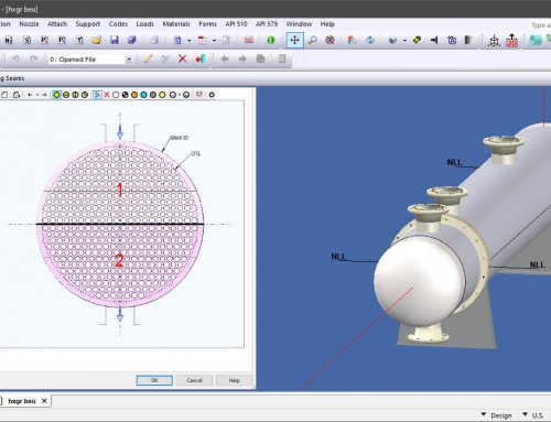
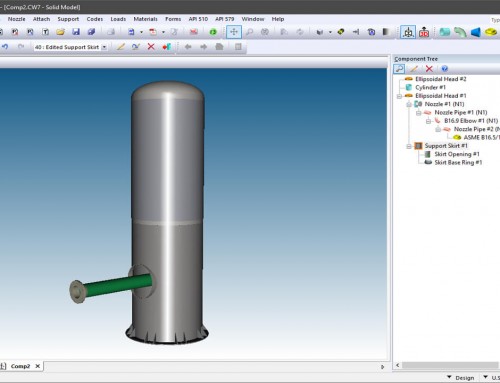
- Design your vessel or exchanger.
- Select your test basis in Set Mode Options > Defaults > Testing.
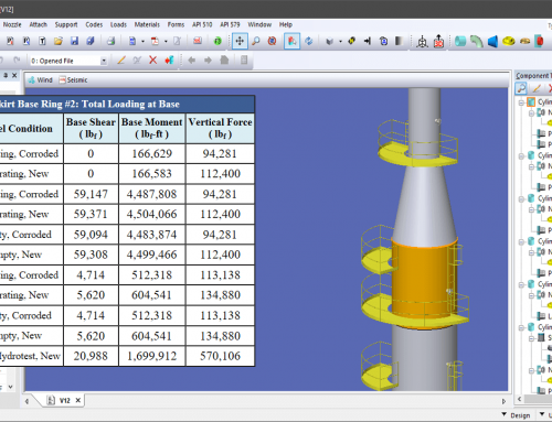
- Press F3 to generate the Code calculations. Click “Hydrotest” on the left to view the report.
- Check for over-stressed components and revise your design as necessary. To speed your review, any over-stressed components will be listed in the Deficiency Report.
- To avoid brittle fracture, it is good engineering practice to ensure that the proposed test temperature is not too cold. If it is, a UG-99(h) warning will be listed in the Deficiency Report. Generally, the thicker the vessel the more important this check becomes.
The Limiting Hydrotest Stress Criteria
ASME VIII-1 does not provide guidelines for determining allowable stress values for the test condition so the following method is used by COMPRESS and INSPECT. It is taken from the 2004 Edition of ASME VIII-2, paragraph AD-151.1. If needed, you can define a different percentage of yield allowed at test in the Set Mode Options > Defaults > Testing dialog.
(b) Pm + Pb ≤ 1.35 * Sy for Pm ≤ 2 / 3 * Sy
(c) Pm + Pb ≤ 2.2 * Sy − 1.5 * Pm for 2 / 3 * Sy < Pm ≤ 0.8 * Sy
In the equations above, Pm is the primary membrane stress and Pb is the primary bending stress. The yield stress Sy is taken as the smallest of the shell, reinforcing pad or nozzle neck Sy values.
The discontinuity stress state at a nozzle includes both primary membrane and bending components. As equation (a) governs for shells and either equation (b) or (c) governs for nozzles, the test allowable may be different for nozzles and shells even when they are made from the same material.
+1 (941) 927-2670 | sales@codeware.com