What’s New in COMPRESS 2016 Build 7600 Webinar Q&A

Bend schedules can be added through the Codeware Interface. There is a pre-installed “Bend Schedule” table available.

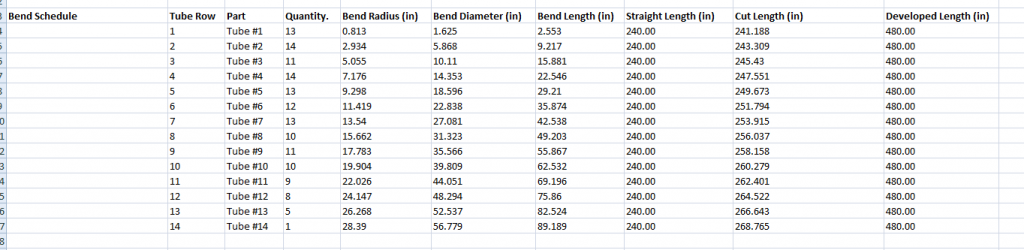
They may also be obtained by using the COSTER Utility which is now available from our support center.

Bend Schedule in SOLIDWORKS

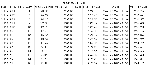
Bend Schedule in COSTER Utility

Depending on the required Code of construction you may be able to use COMPRESS. Vessels are analyzed to ASME VIII-I (Or B31.3 in our Piping document).

Silos will typically have a Cone top on it. COMPRESS has the ability to model and analyze cones (transitions). Transitions can be modeled at any angle (after 30 half apex angle COMPRESS performs a U-2(g) analysis automatically for you). COMPRESS uses the Appendix 1-5 and 1-8 rules to investigate the cone cylinder junction. Common vessels we see with cones would be kettle type heat exchangers, tall towers, etc. If you have a general arrangement drawing you can send I can have one of our engineers review it to make sure COMPRESS will meet your needs.

You can model these from the ‘Component’ menu >> Transition. For it to be ‘Toriconical’ you can add a knuckle and a flare to the transition.
Jacketed vessels are actively being worked on and we anticipate a release this year.
Depending on the type of nozzle you are trying to design we may need to see a detailed drawing. Please feel free to contact our support staff for this and we can address it for you.
Not currently but additional fittings will be added in the future.
Yes, once the UG-34 cover is attached to the B16.5/16.47 flange you can add multiple openings (or one) to the cover.
As per ASME B16.11 paragraph 6.3.1, “The body or end wall thickness of threaded fittings shall be equal to or greater than the minimum values, G, as shown in Tables 2 through 4 or Tables I-2 through I-4.” The majority of the dimensions for threaded couplings are found in Table I-4. As per Table I-4 Threaded Fittings General Notes (c), “The wall thickness away from the threaded ends shall meet the minimum wall thickness requirements of Table I-2 for the appropriate NPS and Class Designation fitting.”

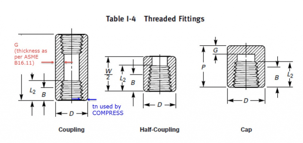
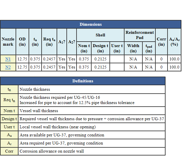
As mentioned above, ASME B16.11 defines the minimum wall thickness away from the threaded ends (the thickness of the unthreaded hub). However, COMPRESS reports a different value for the wall thickness. This is due to COMPRESS calculating the wall thickness at the end of the threaded coupling, not away from the ends as mentioned in Table I-4 General Note (c). The COMPRESS default thickness at the ends of the threaded coupling is found as ½*(Coupling Outer Diameter – Pipe Size Outer Diameter). This value will be thinner than the “G” value. However, a thinner value is desired in order to be conservative when performing the UG-37 reinforcement area calculations and UG-45 nozzle neck thickness calculations (COMPRESS uses the Code Interpretation VIII-1-83-217 for the UG-45 equivalent minimum thickness). Although COMPRESS uses the threaded end thickness, the actual thickness through the unthreaded hub should still match “G” from Table I-2 for the appropriate NPS and class designation.

The figure below specifies the thickness COMPRESS is reporting compared to the minimum wall thickness defined by ASME B16.11.

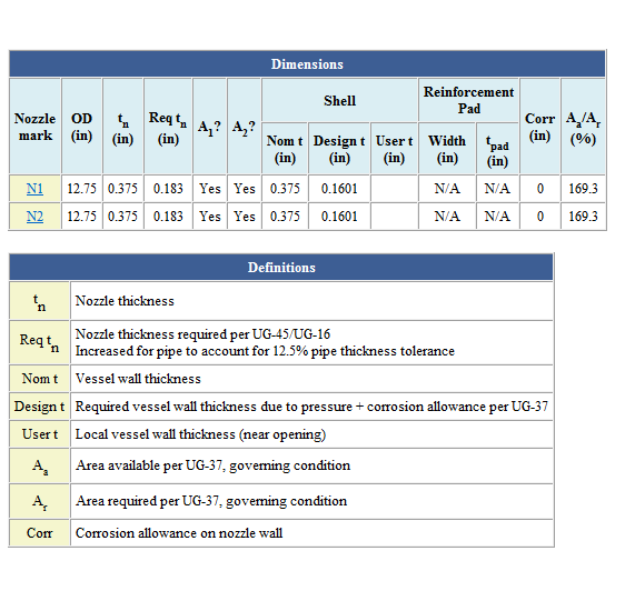
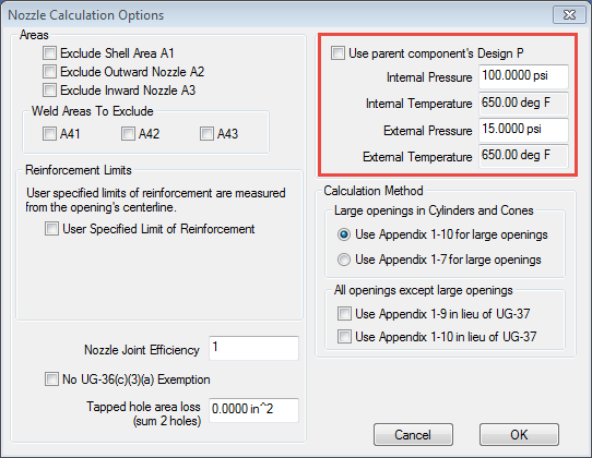
Note that the nominal thickness input field is “unlocked”. The designer can elect to change this dimension as necessary.

COMPRESS does not currently have the ability to model obround sight glasses.
Yes, you may attach multiple openings to the cover.
There are no plans currently but you can conservatively model this as a radial opening using the largest chord opening as the diameter. If you are interested in further details on this please contact our support and we can explain this further.
Option Turned On:


Option Turned Off:

Notice the difference in ‘Req’d tn’, and the ‘Design t’. This will vary on every vessel. It could be a setting you may have set. Please feel free to contact us and we can review the file you have in question.

This feature is actively being worked on in a joint effort with Intergraph.
COMPRESS provides for all ASME Section VIII, Division 1 Code Editions and Addenda to 1995. By selecting any Code Edition or Addenda, all the applicable Code rules from that selection will be applied to the vessel design, including the allowable stresses from Section II Part D for that year’s selection.

For Code Editions prior to this we recommend setting up user defined materials and entering in the Allowable from that Code Year. It was common in the 1960’s for example to have “Section II-D” printed directly in the Code Book.

You can copy and paste the BOM from COMPRESS into Excel. Or you can download the COSTER Utility from our support center and load in the XML3D files which will then create a BOM for you.
We do not currently address Appendix Y but it is on our request list.
Yes, you can change the orientation of a vessel by going to the Action menu and selecting ‘Set Datum’. In this dialog you can adjust the orientation.
The dimensions of the flange are from the B16.5 standard. The cover is dimensions based on the thickness requirements from UG-34.
Yes, we plan to add more fittings into COMPRESS as time permits.
You can specify loads from the “FEA Details” dialog (second screen of the nozzle dialog). The nozzle would then need to be to analyzed using FEA. The reason for this is because WRC-107, WRC-527, and WRC-297 do not address this type of construction (attachments to flat plates).
Yes, this can be added from the ‘Attach’ menu. On this menu you can select ‘Piping’.
Yes, we will be adding more fittings in future builds of COMPRESS.
There are two ways to proceed. The most common way is by adding them through the ‘WRC Local Stress’ dialog (Nozzle dialog). Here you can enter in the loads to the WRC-107 or WRC-537 convention. COMPRESS will then analyze the nozzle and produce the results in the detailed report.

The second way is through the ‘FEA Details’ (Nozzle dialog). Once the loadings are entered you can run the FEA and results will be in the output calculations.

There is also an option to perform the WRC-297. This is run through our FEA interface. In the options you can select to run the WRC-297.

Send us in a drawing of the nozzle and we can recommend how to proceed.
You can check the nozzle using the WRC-107 or WRC-537. You can enter in the load(s) on the ‘WRC Local Stress’ dialog and review the results in the output report.
Yes, you can enter ‘Distance’ value which will offset the nozzle from the center of the cover.

Elbows can be added to nozzle types 1 to 8.
Elbow connections are currently available for nozzles.
COMPRESS is designed for modeling and analysis of shell-type pressure vessels subject to ASME Boiler and Pressure Vessel Code Section VIII, Division 1 (and optionally Division 2). Any type of process vessel that utilizes pressure components such as cylinders, cones, and heads can be modeled in COMPRESS. We are aware that some clients use COMPRESS for design of similar structures that are subject to other design Codes.
No but currently have plans for this feature.
ASME Section VIII Division 1 permits certain standard pressure components to be accepted based on the relevant Standard. Such components are listed in UG-44. This paragraph accepts ASME B16.5/B16.47 flanges as a standard pressure component based on their published pressure-temperature rating. UG-44 does not list flanges produced to other Standards such as API, AWWA, DIN, or JIS, etc. Consequently, these flanges must be analyzed and accepted by Appendix 2.
Yes. We are currently working on adding these components to our heat exchangers.
This is a very common question.

ASME B16.5/B16.47 flanges are accepted by COMPRESS based on their published pressure-temperature rating. But note that many “standard” flanges do not meet their pressure-temperature ratings when analyzed per Appendix 2. In this case, COMPRESS will increase the flange thickness as required. These are Code issues over which we have no control. B16.5 describes in some Appendices how the pressure-temperature ratings are determined. The basic stress analysis is not much different from Appendix 2 but due to need to account for broad range of gasket types and diameters the pressure ratings may not correspond to the MAWP as by Appendix 2 analysis. For example, we have found through analysis that “stocky” or “husky” flanges, say a 6″ Class 1500 flange, may have MAWP per Appendix 2 that is far greater than the published pressure rating in B16.5. But “skinny” flanges, say 24″ Class 150, may have MAWP per Appendix 2 that is far less than the published pressure rating in B16.5.
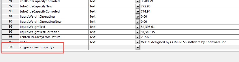
Yes, you can multiple openings onto the cover.
These designate our versions of COMPRESS. When we release a new version (Or Build) we increment them. The first digit designates that it is from the COMPRESS 7000 series. The second digit refers to the current year. The last two digits refer to the release number from within that year.

So for 7600:

7 – Refers to the series of COMPRESS
6 – Refers to the current year (2016)
00 – Refers to the release version within the current year

Yes. Individual workstations can update COMPRESS independently. The network license refers to the fact that the license key resides on a server on the network (not necessarily the network server) and apportions the licenses on demand. Note that we recommend that all workstations be updated to use the most current build of COMPRESS.
Yes, you can add two standard lift lugs with longitudinal orientation or up to 6 in the circumferential orientation.

If you are requiring support lugs COMPRESS does not currently offer this capability.

If piping loads are significant enough to affect the supports they should be added as ‘Global’ loads from the loads menu. These will then be considered in the support calculations.

We have discussed translating the WRC loads to the supports. However, we felt this would needlessly complicate the user-interface and the amount of information that the designer would have to enter (it would be important that all nozzle loads are entered in strict orientation, and what loads acted concurrently) for very little gain or benefit in the reliability of the analysis.

Yes. Flanged and Flued Expansion joints can be designed to any of the TEMA Editions (7th, 8th, or 9th) in COMPRESS. Or you can design Appendix 26 Bellows type expansion joint. The expansion joints are handled through our heat exchanger module.
At this time there are no plans to implement ASME Boiler and Pressure Vessel Code Section I (Power Boilers). We are aware that a number of COMPRESS users use the software to design for this Code, making manual adjustments as-necessary. They can do so because of the similarity of Section 1 and Section VIII Division 1.
Yes, the presentation is posted online.
COMPRESS investigates the rules for radiography. However, COMPRESS does not address the rules from Section V.
PWHT is the abbreviated form for Post Weld Heat Treatment.
COMPRESS can also design tubesheets to the TEMA 7th, 8th, or 9th Edition(s).
COMPRESS does not provide options for platforms and ladders on horizontal vessels. You can add vertical loads to the vessel to account for the weight of such platforms.

Option for platforms/ladders for horizontal vessels is already on our request list. It is a low priority item and may not ever be implemented. Platforms for horizontal vessels are of too many different possible configurations to make it practical to incorporate this feature easily into COMPRESS. Platforms for vertical vessels are generally (but not always) circular or semi-circular; whereas for horizontal vessels there are too many possible “footprints”. Also, for horizontal vessels the portion of the platform weight supported by each saddle depends upon how and where the platform is attached to the vessel. The level of detail required to completely define the platform and its effect on the vessel design is very high.

Yes. You can change the ‘Identifier’ in COMPRESS before exporting the XML3D file.
COMPRESS currently shows the pads in the ‘3D’ view. The welds are not currently shown but will be addressed at a later time.
This is on our development list to have the welds shown on the model. The weld values are passed over to the custom properties for the nozzles.
The WRC-297 has been in COMPRESS for a long time. COMPRESS includes analysis by WRC bulletin 297 in the FEA-Nozzles feature. “Check” the option on the FEA control dialog (at run-time) to use WRC-297.
This is currently on or development list.
We are actively working on adding more of these types of components to our solid model.
COMPRESS provides a number of non-pressure attachment components under the “Attach” menu item. These includes clips/lugs, piping, platforms, ladders, etc. These are provided for the purpose of accounting for the weight of these attachments (and any bending moment due to the eccentricity of the weight)
Any internals modeled in COMPRESS will be exported to the solid model. If you need specific internals you can access SOLIDWORKS 3D Content Central. Here you will be able to search for various components (pumps, internals, etc) that you can add to your model.
Yes. You can add these features to the model once it has been exported. Our developers are working toward improving our model to include these features.
We are actively working on this. We don’t have a set release for this feature yet.
I suggest looking into Genius Solutions (http://www.geniuserp.com/). They may be able to help with your ERP system.
We do not plan to extend the Codeware Interface to support Siemens NX at this time. But you can load in the neutral file formats such as ACIS or STEPS files which you can export from COMPRESS.
The models imported into SOLIDWORKS (or Inventor) are native SOLIDWORKS files. All the features used to create the models are included (sketches, features, etc).
Currently the models are grounded. Mates are currently being addressed by our development team.
COMPRESS includes the rules of UG-39 for the openings in UG-34 cover. To have this accepted as a U-2(g) analysis I suggest contacting your local jurisdiction on their requirements for this.
Absolutely! We’ll be hosting another webinar to go over this in February.
We don’t fully understand your question. Please contact Codeware for further clarification.
COMPRESS does not currently offer the ability to insert double tubesheets.

Historically, double tubesheets were used to try and prevent leakage between the shell and tube side fluids. The more modern practice, which eliminates the need for double tubesheets, is to specify tube to tubesheet seal welds with leak testing performed using one of the new mass spectrometer leakage testing devices. This can save companies money when buying replacement exchangers too.

You can convert the plates to ‘Sheet Metal’ and then roll them out. We are currently working on importing the models as sheet metal for this reason.
The joint detail for UW-13.2 is currently on our list.
Both SOLIDWORKS and Inventor both offer simulation packages that can be used to evaluate the vessels. For more information contact their re-sellers for more information.
No. We are developing these capabilities in our Codeware Interface.
There are no plans currently but you can conservatively model this as a radial opening using the largest chord opening as the diameter. If you are interested in further details on this please contact our support and we can explain this further.
This is coming in a future build. We are currently looking into this feature. This will allow for shell rollouts to be produced.
This feature is already in COMPRESS. On the nozzle dialog you can access the ‘Nozzle Calculation Options’. There is an option to specify a different nozzle pressure.

This is coming in a future build. We are currently looking into importing the model as ‘Sheet Metal’ so that shells can be rolled out.
Currently the models are grounded. Mates are currently being addressed by our development team.
No. Our development efforts are currently focused on SOLIDWORKS and Inventor.
It is available now. You can update to our 2016 products by visiting our support center and downloading them.