Cree dibujos automáticamente con el Interfaz Codeware®.

La interfaz Codeware (CWI) ahorra tiempo a los diseñadores y reduce los errores al generar rápidamente modelos sólidos de recipientes a presión de SOLIDWORKS® o Inventor® a partir de diseños de COMPRESS e INSPECT. También incluye Drafter 3D, una función que genera dibujos de recipientes a presión a partir de modelos sólidos creados por CWI. El CWI está disponible como complemento para SOLIDWORKS o Inventor y se suministra sin coste adicional para los clientes de Codeware. Gestiona los datos asociados a los archivos de diseño importados mediante el uso de iProperties (Inventor) o Custom Properties (SOLIDWORKS). El CWI también admite el uso de técnicas avanzadas de modelado de sólidos, como representaciones de ensamblaje, configuraciones, características, bocetos, chapas metálicas y Mates.

La interfaz de Codeware crea automáticamente dibujos de montaje de haces de tubos

COMPRESS Dibujos

  • Los dibujos de detalle de las láminas de tubos se generan mediante la interfaz de Codeware
  • El apéndice 2 de los dibujos de detalle de las bridas personalizadas se genera mediante la interfaz de Codeware
  • Los planos de detalle del soporte de la silla de montar se generan mediante la interfaz de Codeware
  • Los planos de disposición general se generan mediante la interfaz de Codeware

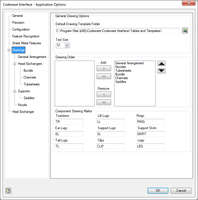
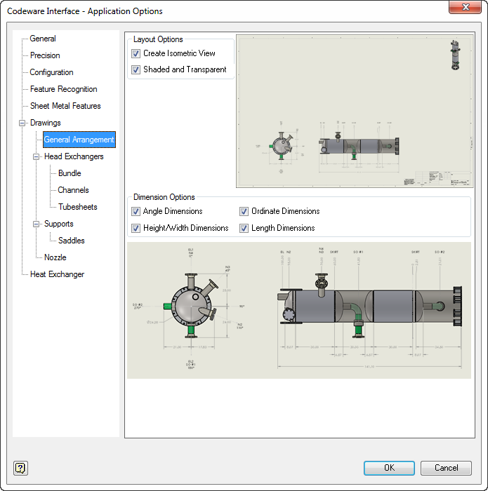
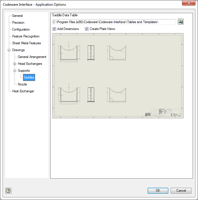
Opciones de dibujo de la interfaz de Codeware

  • Disposición general

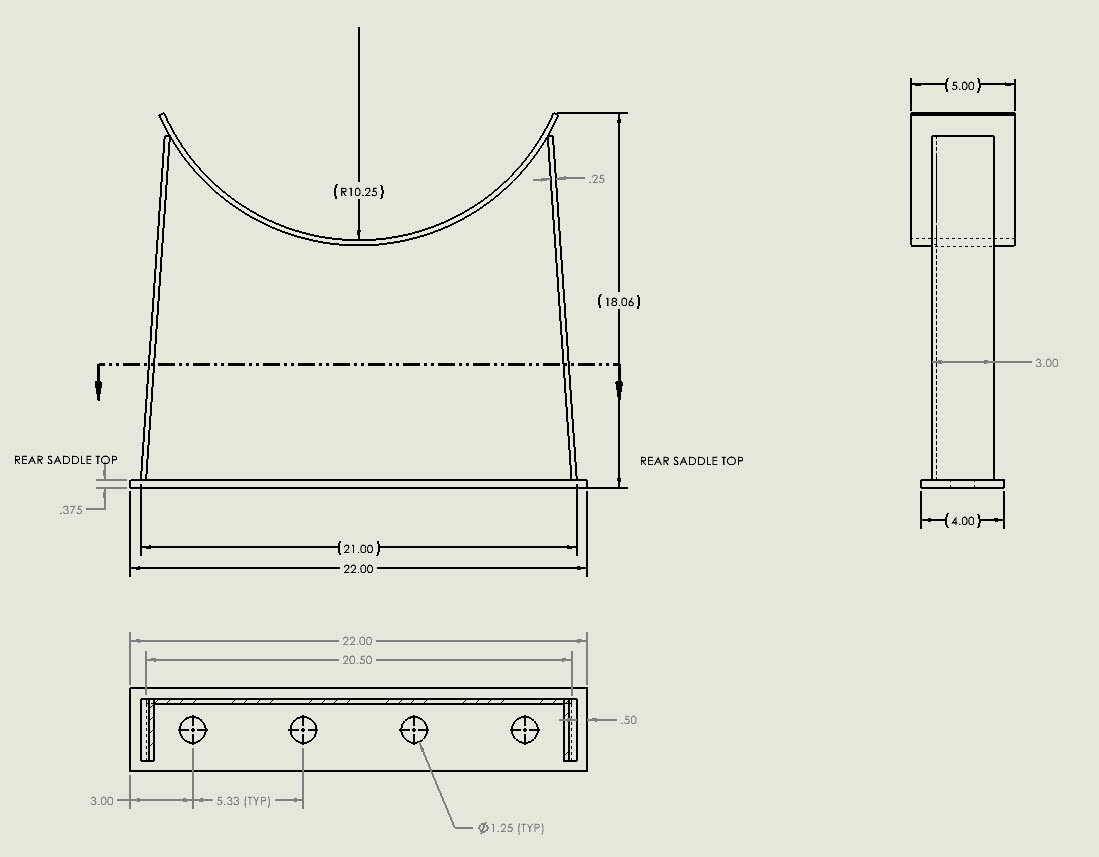
Cree y personalice eficazmente las vistas frontal, lateral e isométrica de sus embarcaciones. Las vistas frontal y lateral incluyen el ángulo de fijación, la ordenada, la longitud junto con las dimensiones de altura/anchura.

  • Intercambiador de calor

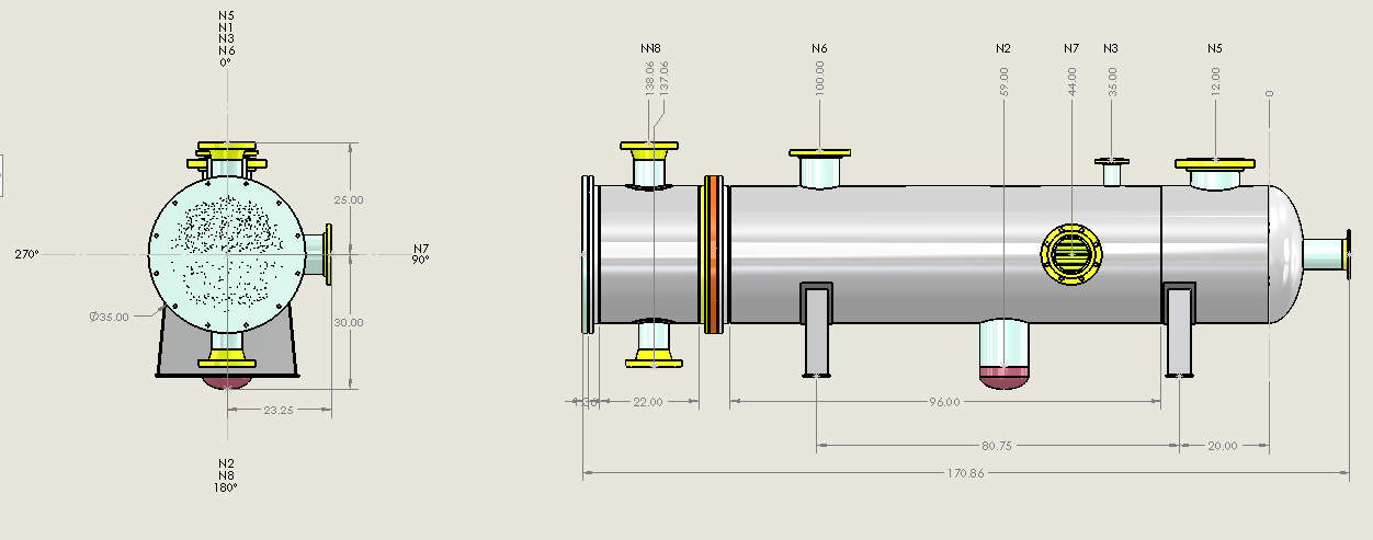
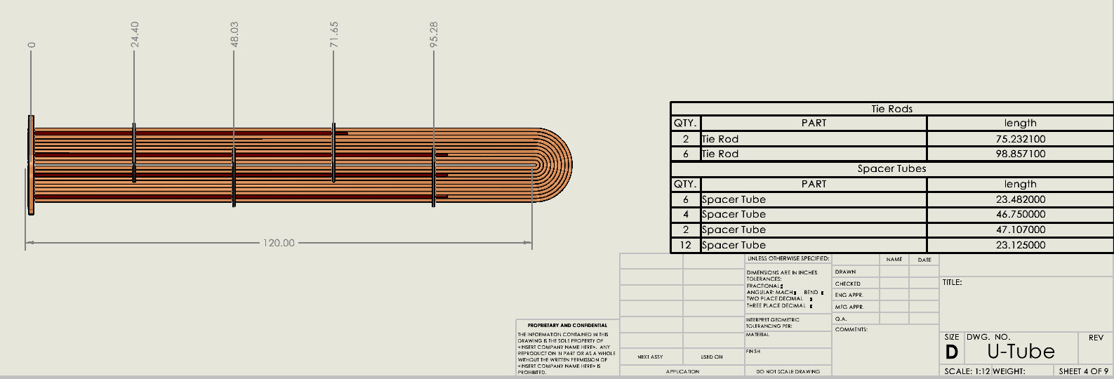
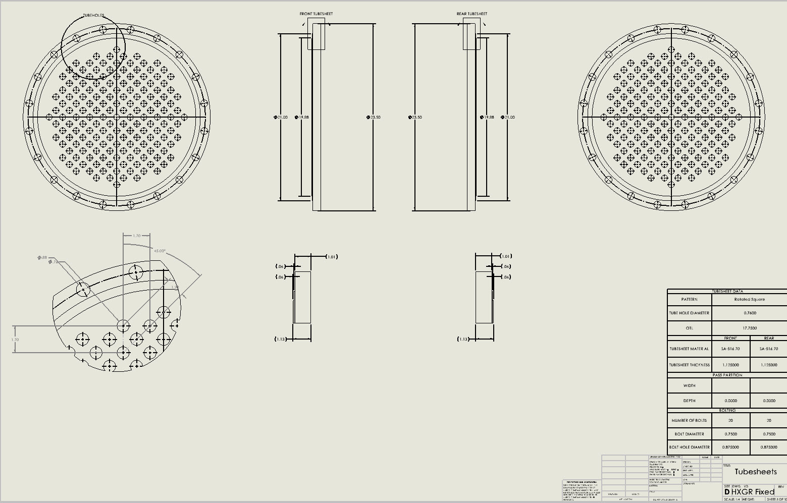
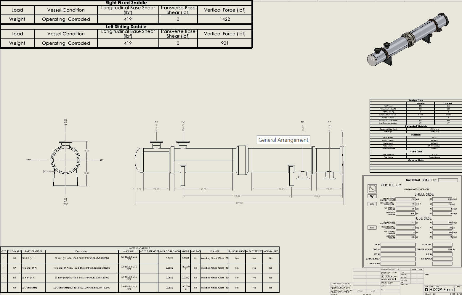
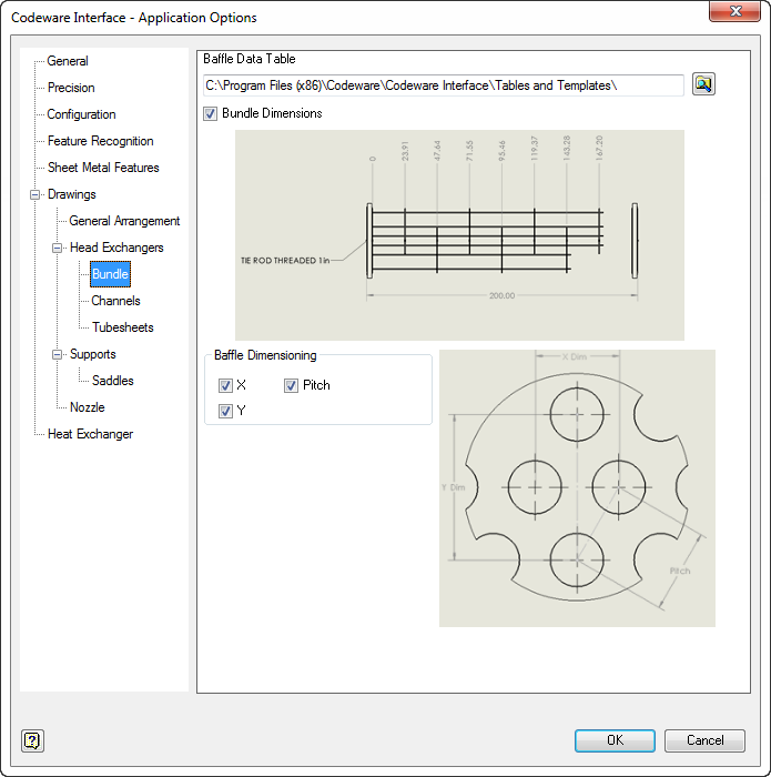
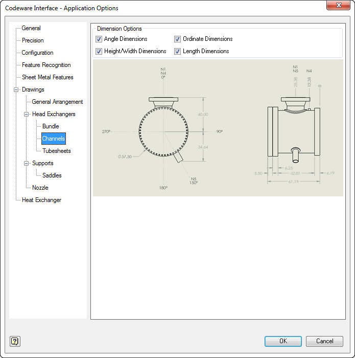
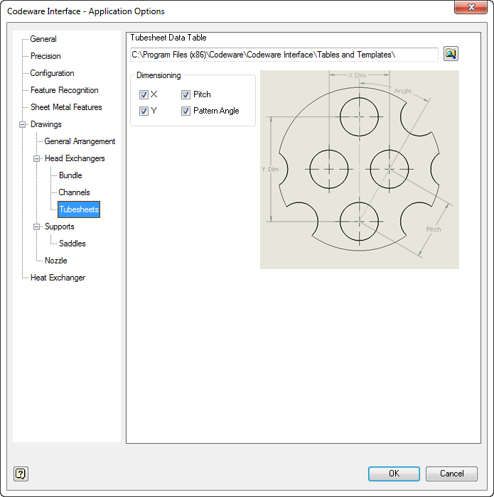
Los planos de intercambiadores de calor personalizables incluyen haces, canales y placas tubulares. La altura, la anchura, el grosor y las dimensiones de la disposición de los tubos están disponibles para su aplicación automática.

  • Brida a medida

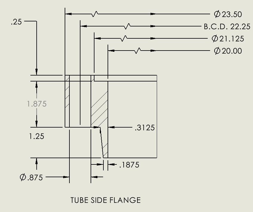
Los dibujos de detalle de las bridas personalizadas incluyen automáticamente el identificador del componente y las dimensiones.

  • Boquilla

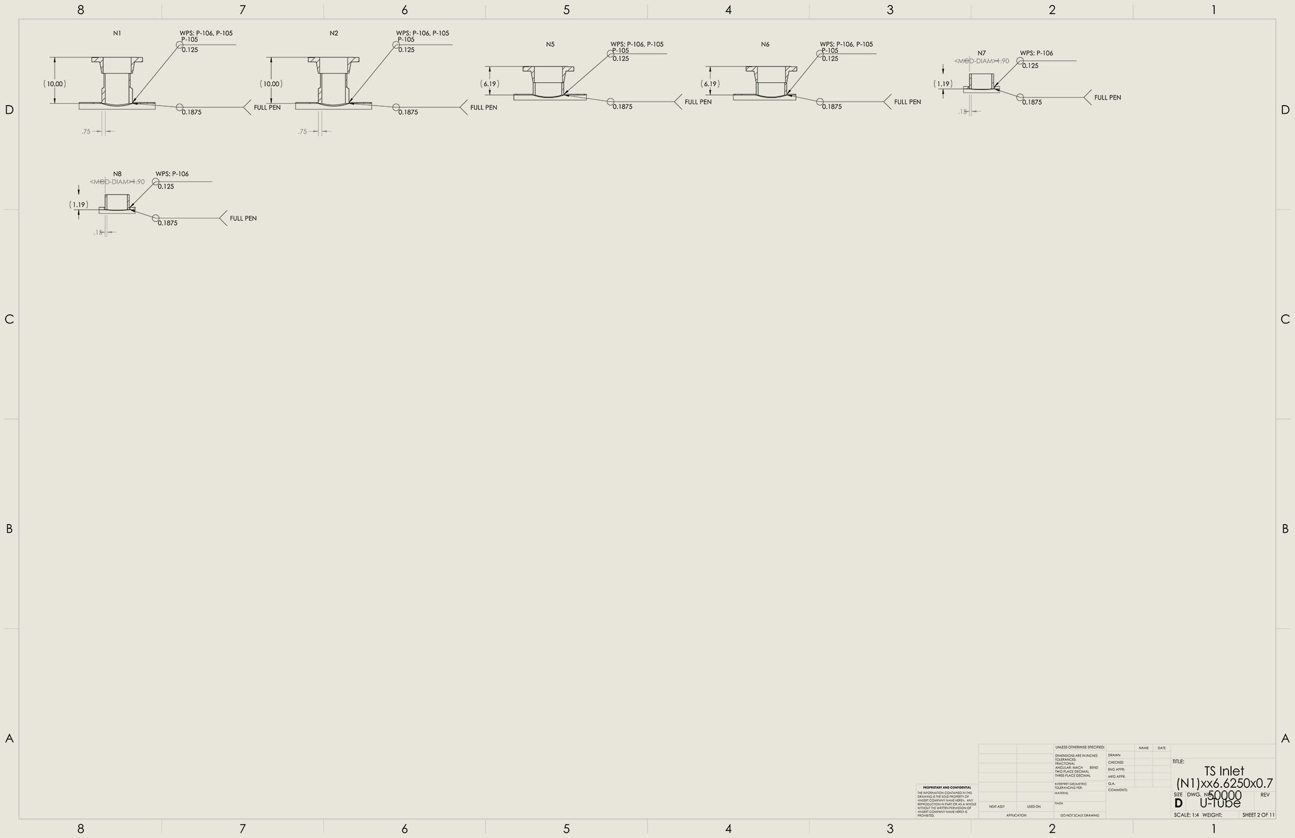
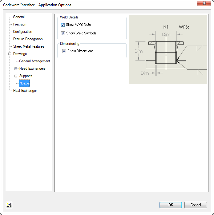
Los dibujos de detalle de las boquillas incluyen automáticamente notas WPS, símbolos de soldadura y dimensiones.

Interfaz de Codeware Incorporaciones recientes

  • Plantillas de dibujo de varias hojas
  • Mejora del rendimiento de Drafter3D
  • Mapa de soldaduras de recipientes a presión
  • Los modelos de tuberías muestran ahora las localizaciones de los defectos API 579

Aspectos destacados del diseño de los recipientes a presión COMPRESS

Nozzles Simplify the detailing of nozzle attachments with flexible and intuitive nozzle design capabilities. Finite Element Analysis Built-in FEA for Nozzles, Clips and TEMA Expansion Joints. API 650 Storage Tanks Modeling storage tanks is easy as COMPRESS guides you through an intuitive design wizard. Vacuum Rings Drag-and-drop vacuum rings and quickly see how the external pressure rating changes. Quick Design Speed up the process of pressure vessel modeling with Quick Design mode. Productivity Software packages like COMPRESS exist to increase productivity and save Engineering hours. Heat Exchanger Perform ASME UHX and TEMA calculations independently or leverage the bi-directional interface with HTRI. Division II As Division 1 increasingly references Division 2 provisions, many companies are transitioning to Division 2 rules to capitalize on material savings. MDMT Rules of UCS-66 The rules of UCS-66 guard against vessel failure by brittle fracture, a low probability, high consequence event. External Pressure Design Simplify the complexity of the
UG-28 rules for external pressure design and vacuum rating.
Jacketed Vessels Design both conventional and half pipe jacketed vessels. Vessel Wizard The Vessel Wizard speeds pressure vessel design by creating complete pressure vessel models with minimal input. COSTER Import files from COMPRESS and create user customizable pressure vessel cost estimates in spreadsheet format. Flange Design Create optimized Appendix 2 flange designs with minimal time and effort and account for loadings on standard B16.5/16.47 flanges. Weld Seams Designers can visually confirm good practices such as staggered longitudinal seams. Lifting & Rigging Use an accurate weight, the correct center of gravity, and apply the actual section properties. Modeling + Drawings The Codeware Interface includes Drafter 3D, a feature that auto-generates 2D pressure vessel drawings. Related Codes COMPRESS implements a wide range of related engineering methods, codes and standards. Design Mode Save time by reducing the trial and error iterations that would otherwise be required when designing pressure vessels. Rating (Analysis) Mode The COMPRESS Rating Mode takes your design and determines the vessel’s MAWP, MAEP and MDMT. Hydrotest Performing hydrotest stress calculations in the design stage prevents equipment damage during hydrotesting. Hillside Nozzle COMPRESS saves time by calculating chord openings and governing planes of reinforcement automatically. ASME Editions Older ASME Codes are retained in all COMPRESS releases so you can always use the latest software. Automatic Liquid Levels COMPRESS eliminates the need to manually calculate each vessel component’s liquid static head. Global External Loads The Loads Menu allows designers to easily consider global external loads when sizing pressure vessel supports. Clips and Lugs Quickly add in various structural shapes to complete your design. Multi-Chamber Vessels Certain industrial processes require pressure vessels with multiple chambers operating under different design conditions. Appendix 46 Produce more economical Div 1 pressure vessel designs with increased accuracy from the Div 2 design by rule equations. Manufacturer's Data Reports Simplify the creation, submission and management of ASME Manufacturer’s Data Reports and NBIC Repair and Alteration Forms. Support Skirt Openings Specify piping connections to vertical vessels that require additional piping and openings cut out of the support skirt. Branch Connections Reduce pressure vessel welding and material costs by modeling tees in COMPRESS. Foundation Loads Summary Break down the loads for the specified vessel operating conditions including weight, wind, seismic, and vortex shedding. Shipping Saddles COMPRESS provides a shipping saddle option based on the industry standard Zick Analysis. UG-80 and UG-81 COMPRESS automatically provides out-of-roundness tolerances that must be maintained during pressure vessel fabrication. Nameplate Design Every pressure vessel is required by Code to have a nameplate. COMPRESS handles this by including a convenient nameplate option. Fatigue Screening Quickly enter fatigue data to determine if a fatigue assessment is required. WRC 537 Nozzle Loads Check stresses on nozzles using WRC 107 and WRC 537 stress analysis for spherical and cylindrical shells.
COMPRESS Quick Design Mode Heat Exchanger designed in COMPRESS Division 2 option in COMPRESS MDMT Rules of UCS-66 Bill of Materials generated from COSTER Flange design in COMPRESS Weld seam wizard in COMPRESS Lifting mechanics in COMPRESS Drafter 3D from Codeware COMPRESS includes related engineering methods, codes, and standards Design mode in COMPRESS Rating mode in COMPRESS Hydrotesting in COMPRESS Hillside Nozzle design in COMPRESS 2023 ASME VIII Code Edition in COMPRESS Automatic Liquid Levels in COMPRESS External Loads in COMPRESS Pressure Vessel clip with pad in COMPRESS Multi chamber pressure vessels in COMPRESS Appendix 46 in COMPRESS ASME Manufacturer's data reports in COMPRESS Support Skirt Openings in COMPRESS Foundation Loads Summary in COMPRESS UG-80 and UG-81 design in COMPRESS Jacketed Vessel in COMPRESS Pressure vessel nozzles Shipping Saddles in COMPRESS Nameplate design in COMPRESS WRC 537 Nozzle Loads in COMPRESS Fatigue Screening in COMPRESS Vacuum Rings in COMPRESS FEA Nozzles in COMPRESS API 650 in COMPRESS Branch Connections in COMPRESS