Finite Element Analysis for Nozzles
ASME nozzle design rules provide guidance for pressure loads only. For nozzles supporting external loads the Code requires additional analysis be performed. WRC-537, also included in COMPRESS, has traditionally been used for this purpose. COMPRESS now includes nozzle FEA for cases where a more accurate solution is required. The COMPRESS FEA engine was created by Codeware to address the detailed requirements of ASME Code stress analysis. It features adaptive meshing, stress error estimating, and is based on advanced Lagrangian 3D elements.
Users can run FEA on existing COMPRESS models or create new designs to quickly obtain detailed stress reports. No additional steps or third party software is required. Mesh exports (.inp files) to other FEA programs such as Abaqus® are available. Exported meshes save time, reduce transcription errors, and can be used for additional verification or further analysis if desired.

See Finite Element Analysis in COMPRESS
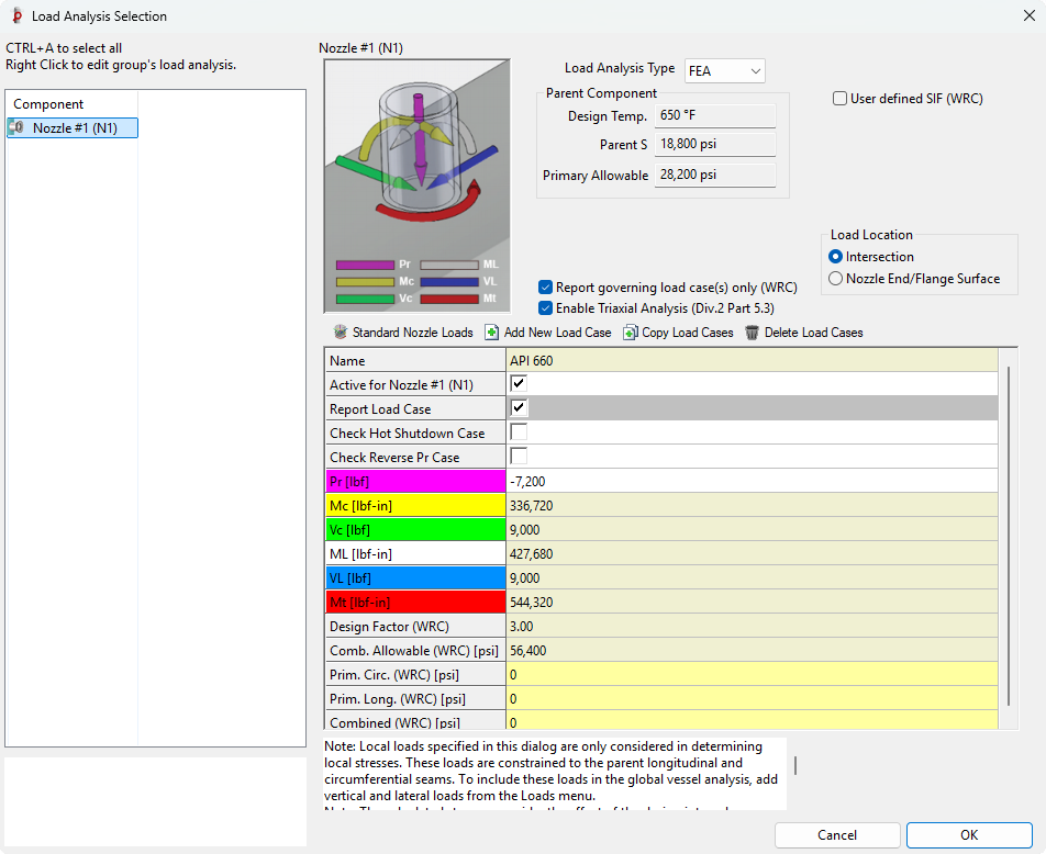
Nozzle Load Analysis
Nozzle FEA is fully integrated into COMPRESS and is accessed from the Nozzle Loads Analysis dialog. Loads can be entered using the traditional WRC convention. A convenient load location option allows loads to be entered at either the shell-nozzle intersection or at the end of the nozzle/flange surface.
Finite Element Analysis Reports
Detailed ASME Division 2 compliant reports are provided. Linearized membrane and bending stresses with their respective allowables (per VIII-2, Figure 5.1) are listed in a handy summary table. The following design information is also reported:
All of this means one complete report.

Interactive Stress Classification Line (SCL) Plot
COMPRESS provides the option to select any SCL on the model to review the details. Simply click on the SCL of interest and results will appear. Results will include calculated Combined Stress, Max and Min Principal Stress, and Von Mises Stress.
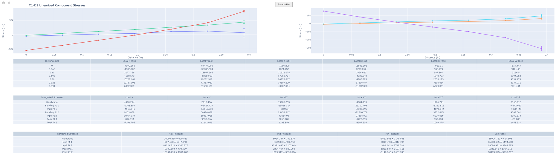
(click image to enlarge)
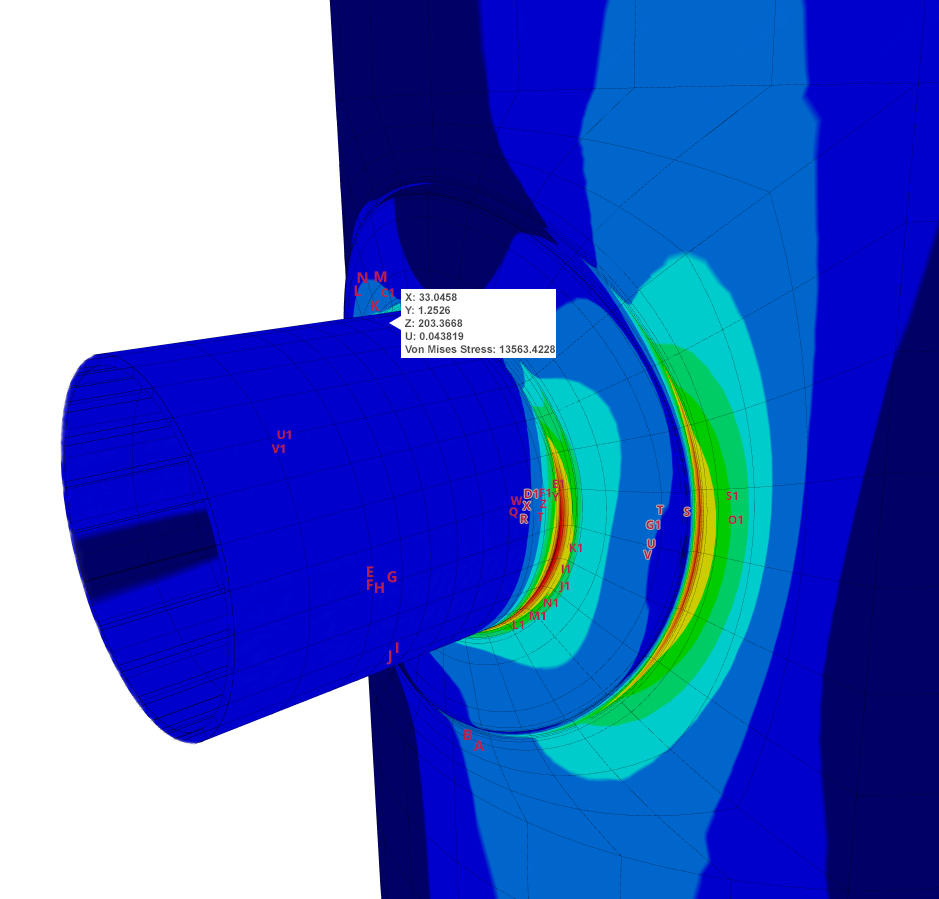
Stress Classification Planes
In addition to SCLs, COMPRESS also provides Stress Classification Planes.
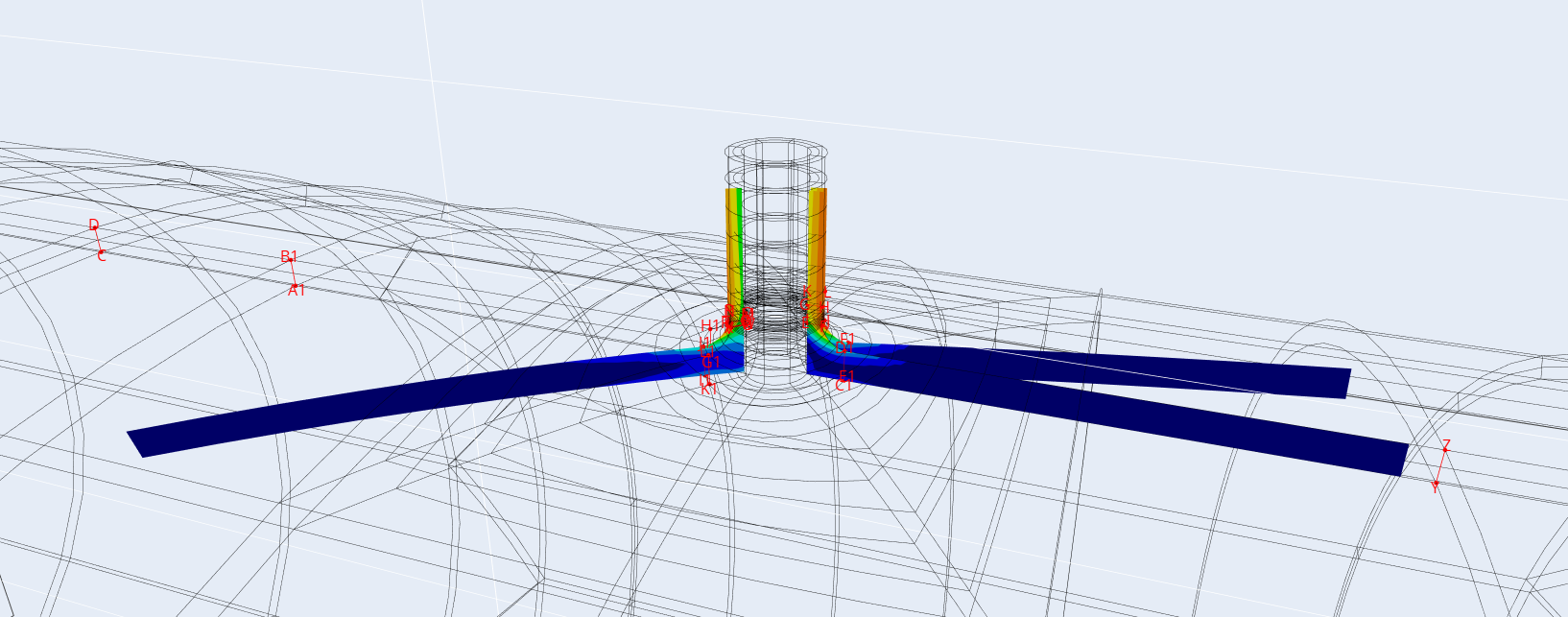
(click image to enlarge)
Stress Error
What is Stress Error and why is it important? Stress Error is the mean difference between un-averaged and averaged stress values. Low stress error is an indication that the mesh and results are stable. Stress error corresponds to stress convergence both locally and globally and is a measure of overall FEA model quality.
The provided stress error reports highlight the location and magnitude of the maximum stress error present in the model. Stress errors less than 5% are typically considered to be acceptable.

Increase Your Capabilities With COMPRESS
UG-28 rules for external pressure design and vacuum rating.


Find Out More
+1 (941) 927-2670 | sales@codeware.com