Finite Element Analysis on Attachments
The ASME Code provides rules for most standard pressure vessel components. But what does one do when there are no rules covering items such as attachments on heads? For example, how do you ensure that the support for your top platform won’t overstress the head?
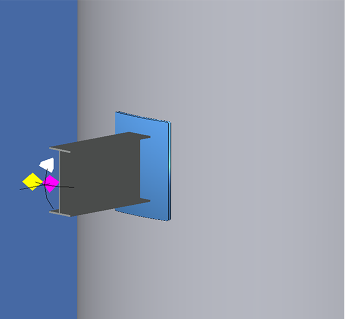
Designers were often left having to perform another stress analysis with 3rd party software which created more work and expense. COMPRESS solves this by including Finite Element Analysis (FEA) capabilities for attachments on pressure vessel heads and cylinders. These attachments include various shapes such as I-Beams, Channels, Tees, Equal/Unequal Angles, and Flat Bars.
The COMPRESS FEA Engine
The COMPRESS FEA engine was created by Codeware to address the specific requirements of ASME Code stress analysis. It features adaptive meshing, stress error estimating, and is based on advanced Lagrangian 3D elements.
Users can run FEA on existing COMPRESS models or create new designs to quickly obtain detailed stress reports. No additional steps or third party software is required. Mesh exports to other FEA programs such as Abaqus® are included. Mesh exports save time, reduce transcription errors, and can be used for additional verification or further analysis if desired.
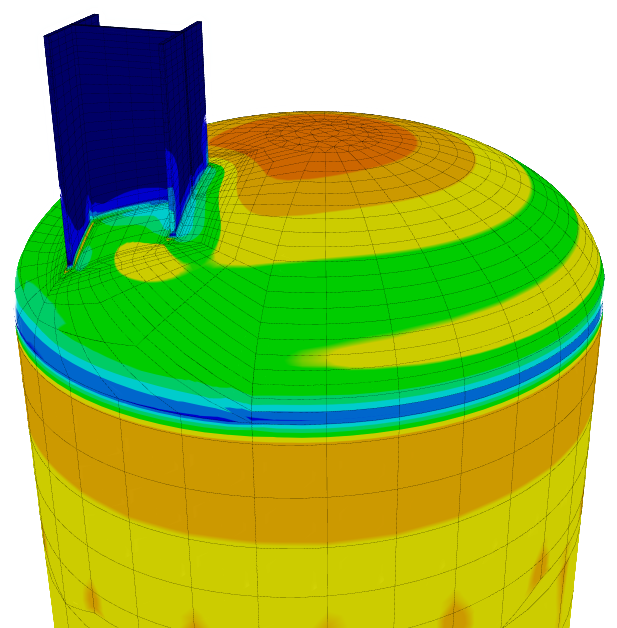
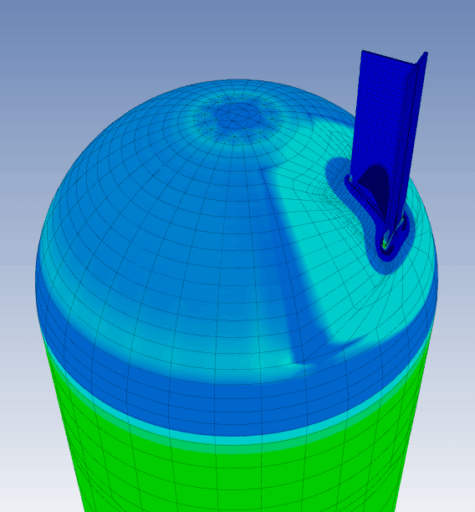
FEA 3D Display
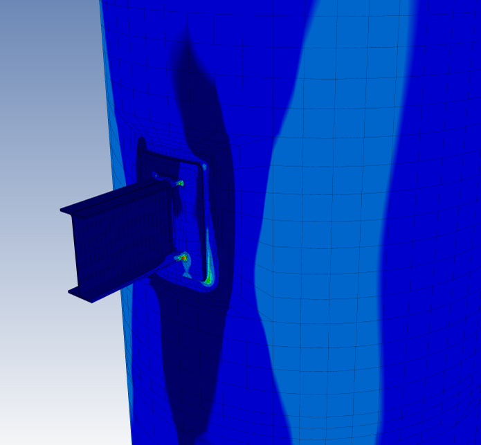
Full detailed reports, suitable for printing, are provided for all FEA runs. In addition, an interactive 3D modeling view facilitates visualization of items such as stress error, SCLs, SCPs and model deformations.
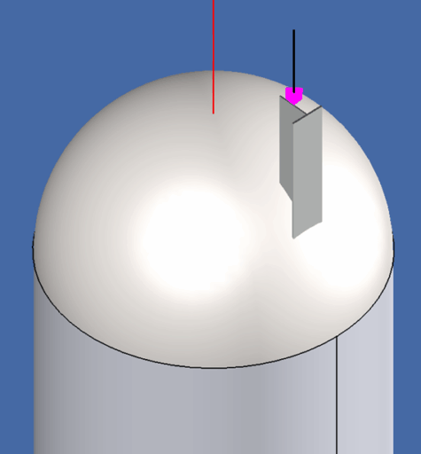
FEA Pad Configuration
Square and circular pad configurations provide accurate, realistic modeling.

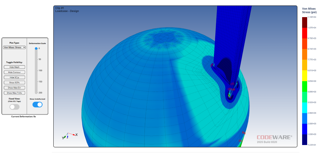
Experience FEA the COMPRESS Way
Explore this interactive Finite Element Analysis (FEA) model to see how COMPRESS evaluates nozzle stress and deformation under pressure. This model demonstrates the detailed stress visualization available within COMPRESS reports, allowing engineers to rotate, zoom, and inspect localized stress concentrations around nozzle junctions. By interacting with this 3D simulation, you’ll gain a deeper understanding of how COMPRESS applies ASME Section VIII design-by-analysis principles to ensure safe and efficient vessel design.
COMPRESS Featured Capabilities
UG-28 rules for external pressure design and vacuum rating.


Find Out More
+1 (941) 927-2670 | sales@codeware.com