UG-37 Nozzle Designing Using COMPRESS
One of the most involved tasks pressure vessel designers face is detailing nozzle openings to comply with ASME UG-37, UG-45, and UW-11. Nozzles serve many purposes including entry and exit points for process fluids, inspection access and drainage. In addition, nozzles support other equipment such as piping, relief valves, pressure gauges and agitators. Careful consideration needs to be given to pressure in combination with any other loads applied to the nozzle connection. COMPRESS easily handles all of these details and offers the most flexible and intuitive nozzle design capabilities available.

COMPRESS Offers the Widest Range of UG-37 Nozzle Design Configurations
COMPRESS Offers the Widest Range of UG-37 Nozzle Design Configurations
The first part of any nozzle design is selecting the nozzle type. COMPRESS provides the most options to choose from. Styles include uniform thickness (pipe), variable wall thickness (heavy barrel, Q-lip), couplings, stud pads, long weld necks, tees, and elliptical manways. Set in, set on and insert attachments are available to define the joint configuration per UW-16.

Nozzle Location and Orientation
Nozzle Location and Orientation
A powerful feature in COMPRESS is the ability to specify nozzles as Radial, Tilted or Hillside (Offset). The additional Code provisions required for Tilted and Hillside nozzles are automatically applied by COMPRESS.


Uniform Thickness Nozzles
Uniform Thickness Nozzles
Q-lips
Q-lips
Often used in the power industry, this type of reinforced opening offers a number of design benefits. “Q-lip” style nozzles provide a butt joint attachment that can be fully radiographed. In addition, these custom forgings do not require fillet welding which enhances their performance when subject to cyclic (fatigue) loads.
COMPRESS provides several configurations when designing Q-lip nozzles. The Q-lip attachment detail may be applied to standard pipe, variable thickness, heavy barrel, and long weld necks.
The convenient Q-lip nozzle reports can be sent to your supplier for faster quoting as well.
")

Economical Nozzle Design Using ASME Appendix 46
Economical Nozzle Design Using ASME Appendix 46
With the recent addition of Mandatory Appendix 46 in ASME VIII-1 users can now take advantage of the modern design rules from ASME VIII-2. In situations where a nozzle does not pass using traditional ASME VIII-1 rules users can select the option to use the more accurate provisions of Appendix 46. A notable feature is that Appendix 46 can be specified for a single nozzle or applied to all nozzles on the vessel.
For more details on how COMPRESS implements Appendix 46 see: Appendix 46 – Using Division 2 Rules With Division 1 Allowable Stresses
Studding Outlets
Studding Outlets
Studding outlets provide a unique type of nozzle design by providing built-in reinforcement and tapped bolt holes that eliminate the need for nozzle to flange welding. Studding outlets also have slightly different requirements per ASME VIII-1 which COMPRESS handles. Simply place the stud pad in the desired location on the vessel and let COMPRESS do the rest.
Blinds can also be added to any studding outlet to complete your design.

Nozzle Connections
Nozzle Connections
COMPRESS includes the handy ability to add B16.11 couplings, B16.9 elbows, reducers, pipe caps, tees, pipe extensions to nozzles. Appendix 2 or B16.5/B16.47 flanges may be attached to nozzles and nozzle extensions as well.


Designing For Piping Loads Using WRC-537 and FEA
Nozzles serve as the entry and exit ports for vessels. With this comes piping connections and pipe loadings. Industry practice for many years has been to use the method from WRC-107 (now WRC-537) to assess the stresses on the shell due to these loadings. COMPRESS provides the WRC Local Stress option for each nozzle with the ability to set up multiple load cases. The API-660 (heat exchanger) load library is available along with the ability to set up your own data set of nozzle design loadings for future use.
Stresses resulting from the loads entered are shown on the WRC dialog which allows the designer to make adjustments as needed. COMPRESS also includes FEA capabilities for nozzles as a standard, no extra cost, feature.
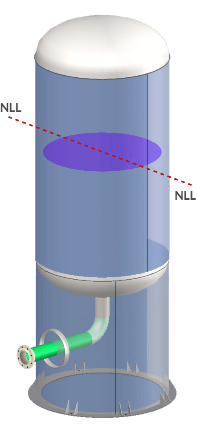
Static Head Determination
Static Head Determination
Once a liquid level has been input, the associated static liquid head is automatically accounted for when designing nozzles (or any component) in COMPRESS. This means that whenever a nozzle is relocated or the liquid level is changed the static pressure is automatically updated everywhere in the vessel design.
Nozzle Plan View and UG-37 Overlapping Limits of Reinforcement
Nozzle Plan View and UG-37 Overlapping Limits of Reinforcement
Certain types of equipment, such as reactors, have many closely spaced nozzles located on the head. An area of concern in these cases is the potential for overlapping limits of nozzle reinforcement. COMPRESS provides a convenient Plan View to see if any overlapping limits of reinforcement are present.


Overlapping limits warnings are provided in the output report and designers can manually adjust the limits for any nozzle. If multiple nozzles meet the size and spacing criteria of UGF-36 then COMPRESS will exempt certain nozzles from the reinforcement requirements of UG-37 (Nozzle Clusters).

Different Pressures Can Be Used
Different Pressures Can Be Used
By default, COMPRESS will automatically use the parent component’s design pressure as the nozzle design pressure. Due to certain processes sometimes a different pressure needs to be used to design the nozzle. In these circumstances COMPRESS provides an option to specify different pressures for the shell and the nozzle.

Quick Nozzle Design
Quick Nozzle Design
COMPRESS offers the ability to quickly add nozzles on any vessel by dragging and dropping. This provides rapid model generation when creating cost estimates or initial starting points for more detailed pressure vessel engineering designs.

Detailed UG-37 Nozzle Design Reports
Detailed UG-37 Nozzle Design Reports
COMPRESS provides fully detailed, professional looking nozzle calculation reports for engineering review. Does your AI or customer want to see how your UG-45 wall required thickness or UG-37 required area was arrived at? COMPRESS has you covered.

Finite Element Analysis for Nozzles
Finite Element Analysis for Nozzles
Unlike competing products, COMPRESS includes built-in FEA capabilities for nozzles as a standard, no additional cost feature. Nozzle FEA is very useful for cases where nozzle geometries exceed the limits of WRC-537 or more accurate results are required.

Increase Your Capabilities With COMPRESS
UG-28 rules for external pressure design and vacuum rating.


+1 (941) 927-2670 | sales@codeware.com