External Pressure Design

External pressure, sometimes called full vacuum, can govern the design of many types of pressure vessels.  Vessels under external pressure fail by buckling collapse.  Because of this, UG-28 rules require the overall vessel geometry to be considered. This is a time consuming trial and error process when done without the right software.  COMPRESS provides the tools and calculations needed to assist designers with this complex task.

All pressure vessels subject to an external pressure of 15 psig or greater must meet the requirements of UG-28.  External pressure design is primarily a function of vessel geometry.  A big factor in this calculation is the unsupported length ‘L’.  If external pressure is requiring vessel sections to get too thick you could reduce the unsupported length by adding a line of support.  COMPRESS addresses this by providing an input called “trial length”.  This allows you to see what a reduced unsupported length would do before adding stiffening rings.

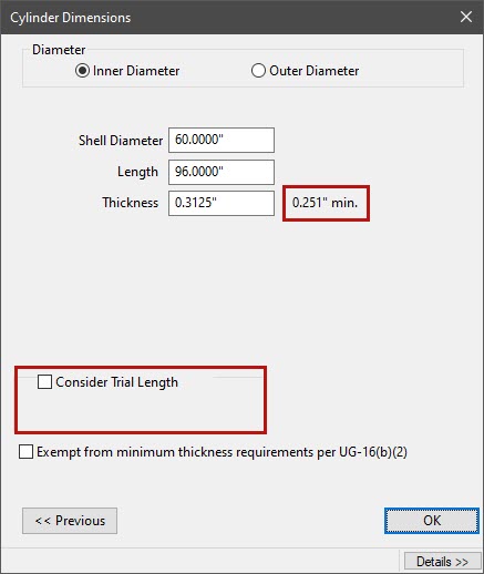
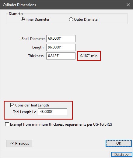
A before and after image on how minimum thickness is impacted when considering trial length.

External pressure design in COMPRESS can use the Bergman Paper to consider additional loads from wind (or seismic) and weight

External Pressure and U-2(g)

Code paragraph U-2(g) requires that external loads acting in combination with pressure on the vessel be considered.  It however does not mandate a specific engineering analysis to use.  For vertical vessels designed for external pressure COMPRESS offers two solutions, Appendix 46 (Division 2 Rules) and the Bergman interaction equations.

The Bergman Paper

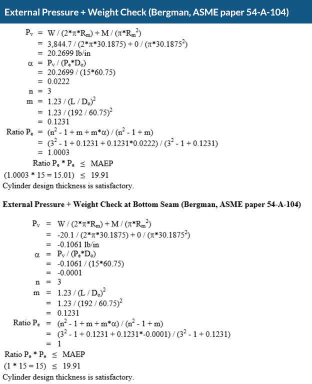
COMPRESS by default uses the method outlined in the Bergman Paper to check for buckling of vessels subjected to external pressure in combination with other compressive loads.  External loads due to wind (or seismic) and weight on vertically supported vessels produce longitudinal compression that adds to the load from external pressure.  The Bergman paper discusses designing pressure vessels for these load combinations and has been used successfully for many years.  The interested reader can find a copy of the Bergman paper here:

The Design of Vertical Pressure Vessels Subjected to Applied Forces – by E. O. Bergman

COMPRESS can analyze external pressure + external loads using Appendix 46 (Division 2)

Allowable Compressive Stress – Appendix 46

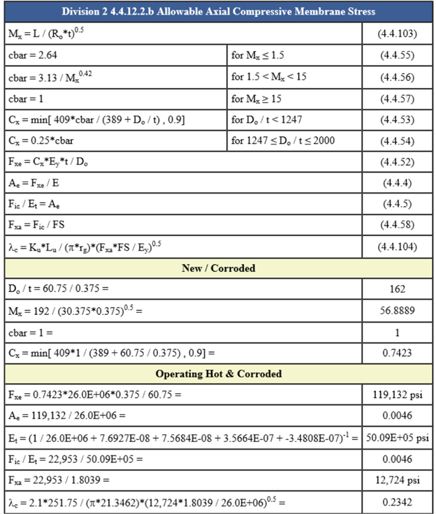
COMPRESS features the option to use the provisions of Appendix 46 for external pressure design.  This allows designers to take advantage of the more accurate equations from ASME VIII-2, Part 4.4 (Division 2).  Appendix 46 requires that Division 1 vessels still be designed using Division 1 allowable tensile stresses.  As buckling is the failure mode for external pressure, the allowable compressive stresses calculated by Part 4.4 are allowed in Division 1 designs.

One advantage of using the Appendix 46\Part 4.4 equations is that they include consideration of external pressure plus axial compression.  This means that a U-2(g) analysis is not required.  Another advantage is that cylinders designed to Part 4.4 are often thinner than those designed with UG-28.  Although Appendix 46 is just as safe as UG-28, some jurisdictions do not yet permit the use of Appendix 46 so it’s best to check before relying on this method.

Out of Roundness Tolerances (UG-80)

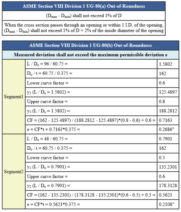
The rules of UG-28 are based on an assumed out-of-roundness tolerance.  Consequently, vessels that are outside of this tolerance pose a potential danger of collapse when subjected to external pressure.  Meeting this out-of-roundness requirement is mandatory per ASME VIII. COMPRESS provides the calculations required by UG-80 to help ensure compliance with the Code.

External pressure designs require UG-80 Out of Roundness tolerances to be met
A COMPRESS external pressure design report showing UG-29 stiffener ring calculations

Stiffening Ring Calculations (UG-29)

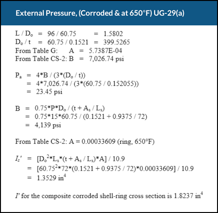
When designing a pressure vessel for both internal and external pressure one approach is to reduce the unsupported length until external pressure no longer governs.  For vessels subject to external pressure only it is often more economical to add intermediate lines of support than to increase thickness.  In either case, adding strategically placed lines of support is the solution. Code paragraph UG-29 addresses the structural requirements for these lines of support (stiffening rings).

In design mode, COMPRESS will automatically select the minimum ring size required to meet UG-29 inertia requirements.  Rings are selected by referring to the built-in structures database alleviating the need to go through a structures list and manually choose the correct type and cross section.

COMPRESS external pressure design can automatically select stiffener rings that meet UG-29 requirements

Selecting Stiffening Rings

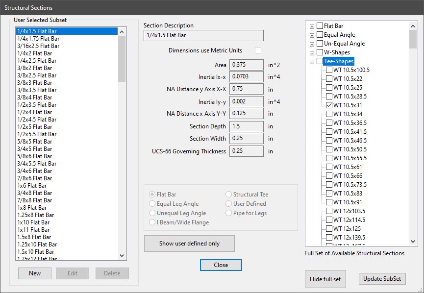
COMPRESS includes a large library of common structural shapes that can be used as stiffening rings.  Users also have the option to add or remove shapes as desired.  Adding shapes makes them available to the COMPRESS automatic selection routines while removing them does the reverse.

User-defined structures of any cross section can also be added.

Cone-to-Cylinder Junctions (Appendix 1-8)

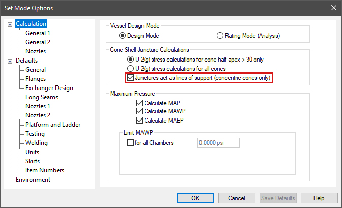
When designing cone-to-cylinder junctions for external pressure COMPRESS users have the option of treating the junction as a line of support.  This will reduce the unsupported length and reduce shell thickness but may come at the expense of additional junction reinforcement.

Cone-to-cylinder junctions must provide sufficient reinforcing area per UG-33(f) and Appendix 1-8.  When the junction also acts as a line of support, these paragraphs additionally require the junction to meet the stiffness requirements (moment of inertia) of Appendix 1-8.  COMPRESS performs all of these calculations saving time and reducing errors.

External pressure cone to cylinder juncture calculation options in COMPRESS

Increase Your Capabilities With COMPRESS

Nozzles Simplify the detailing of nozzle attachments with flexible and intuitive nozzle design capabilities. Finite Element Analysis Built-in FEA for Nozzles, Clips and TEMA Expansion Joints. API 650 Storage Tanks Modeling storage tanks is easy as COMPRESS guides you through an intuitive design wizard. Vacuum Rings Drag-and-drop vacuum rings and quickly see how the external pressure rating changes. Quick Design Speed up the process of pressure vessel modeling with Quick Design mode. Productivity Software packages like COMPRESS exist to increase productivity and save Engineering hours. Heat Exchanger Perform ASME UHX and TEMA calculations independently or leverage the bi-directional interface with HTRI. Division II As Division 1 increasingly references Division 2 provisions, many companies are transitioning to Division 2 rules to capitalize on material savings. MDMT Rules of UCS-66 The rules of UCS-66 guard against vessel failure by brittle fracture, a low probability, high consequence event. External Pressure Design Simplify the complexity of the
UG-28 rules for external pressure design and vacuum rating.
Jacketed Vessels Design both conventional and half pipe jacketed vessels. Vessel Wizard The Vessel Wizard speeds pressure vessel design by creating complete pressure vessel models with minimal input. COSTER Import files from COMPRESS and create user customizable pressure vessel cost estimates in spreadsheet format. Flange Design Create optimized Appendix 2 flange designs with minimal time and effort and account for loadings on standard B16.5/16.47 flanges. Weld Seams Designers can visually confirm good practices such as staggered longitudinal seams. Lifting & Rigging Use an accurate weight, the correct center of gravity, and apply the actual section properties. Modeling + Drawings The Codeware Interface includes Drafter 3D, a feature that auto-generates 2D pressure vessel drawings. Related Codes COMPRESS implements a wide range of related engineering methods, codes and standards. Design Mode Save time by reducing the trial and error iterations that would otherwise be required when designing pressure vessels. Rating (Analysis) Mode The COMPRESS Rating Mode takes your design and determines the vessel’s MAWP, MAEP and MDMT. Hydrotest Performing hydrotest stress calculations in the design stage prevents equipment damage during hydrotesting. Hillside Nozzle COMPRESS saves time by calculating chord openings and governing planes of reinforcement automatically. ASME Editions Older ASME Codes are retained in all COMPRESS releases so you can always use the latest software. Automatic Liquid Levels COMPRESS eliminates the need to manually calculate each vessel component’s liquid static head. Global External Loads The Loads Menu allows designers to easily consider global external loads when sizing pressure vessel supports. Clips and Lugs Quickly add in various structural shapes to complete your design. Multi-Chamber Vessels Certain industrial processes require pressure vessels with multiple chambers operating under different design conditions. Appendix 46 Produce more economical Div 1 pressure vessel designs with increased accuracy from the Div 2 design by rule equations. Manufacturer's Data Reports Simplify the creation, submission and management of ASME Manufacturer’s Data Reports and NBIC Repair and Alteration Forms. Support Skirt Openings Specify piping connections to vertical vessels that require additional piping and openings cut out of the support skirt. Branch Connections Reduce pressure vessel welding and material costs by modeling tees in COMPRESS. Foundation Loads Summary Break down the loads for the specified vessel operating conditions including weight, wind, seismic, and vortex shedding. Shipping Saddles COMPRESS provides a shipping saddle option based on the industry standard Zick Analysis. UG-80 and UG-81 COMPRESS automatically provides out-of-roundness tolerances that must be maintained during pressure vessel fabrication. Nameplate Design Every pressure vessel is required by Code to have a nameplate. COMPRESS handles this by including a convenient nameplate option. Fatigue Screening Quickly enter fatigue data to determine if a fatigue assessment is required. WRC 537 Nozzle Loads Check stresses on nozzles using WRC 107 and WRC 537 stress analysis for spherical and cylindrical shells.
COMPRESS Quick Design Mode Heat Exchanger designed in COMPRESS Division 2 option in COMPRESS MDMT Rules of UCS-66 Bill of Materials generated from COSTER Flange design in COMPRESS Weld seam wizard in COMPRESS Lifting mechanics in COMPRESS Drafter 3D from Codeware COMPRESS includes related engineering methods, codes, and standards Design mode in COMPRESS Rating mode in COMPRESS Hydrotesting in COMPRESS Hillside Nozzle design in COMPRESS 2023 ASME VIII Code Edition in COMPRESS Automatic Liquid Levels in COMPRESS External Loads in COMPRESS Pressure Vessel clip with pad in COMPRESS Multi chamber pressure vessels in COMPRESS Appendix 46 in COMPRESS ASME Manufacturer's data reports in COMPRESS Support Skirt Openings in COMPRESS Foundation Loads Summary in COMPRESS UG-80 and UG-81 design in COMPRESS Jacketed Vessel in COMPRESS Pressure vessel nozzles Shipping Saddles in COMPRESS Nameplate design in COMPRESS WRC 537 Nozzle Loads in COMPRESS Fatigue Screening in COMPRESS Vacuum Rings in COMPRESS FEA Nozzles in COMPRESS API 650 in COMPRESS Branch Connections in COMPRESS

Request More Information

To see how COMPRESS can benefit your organization we invite you to contact us today.