The Importance of MDMT in Preventing Brittle Fracture Failures

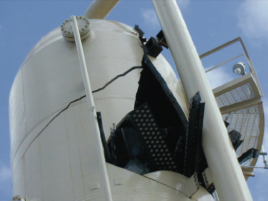
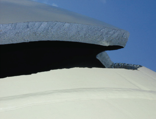
The rules of UCS-66 are some of the most important and yet most misunderstood provisions of the ASME Code.  Because of its importance, minimum design metal temperature (MDMT) is one of just a few critical parameters stamped onto vessel nameplates.  The rules of UCS-66 guard against vessel failure by brittle fracture, a low probability high consequence event.  Brittle fracture failures exhibit “break before leak” behavior and can be catastrophic in that they entail high risks and occur without warning.  Carbon steel pressure vessels are most susceptible to brittle fracture during start up, shut down, hydro test (test water that is too cold) and rapid depressurization (auto-refrigeration).  Given the consequences of this type of failure, all relevant factors listed in UCS-66 need to be properly addressed.  These include consideration of the coldest temperature expected, metallurgy, material thickness, post weld heat treatment, impact testing, applied stress and weld pass size.

COMPRESS helps engineers prevent pressure vessel brittle fracture failures by properly applying the impact test and MDMT rules of UCS-66
COMPRESS dialog showing the impact test settings that affect the UCS-66 MDMT rating performed

How COMPRESS Determines MDMT

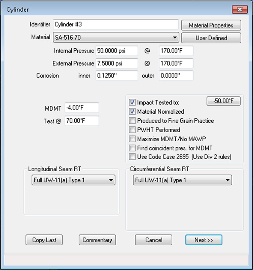
COMPRESS assists the vessel designer by automatically finding the coldest impact test exempt MDMT allowed by Code.  If this rated MDMT is warmer than the required MDMT, the designer is alerted and the limiting component(s) highlighted.  At this point the designer can either change one of the component’s input variables or specify impact testing be performed.  As impact testing is expensive, it is usually called for only when it is a Code or local jurisdictional (CSA) requirement.  COMPRESS automatically:

  • Determines if the selected material falls under the provisions of UCS-66.

  • Accounts for different materials by using the correct impact test exemption curve from Figure UCS-66.  This includes consideration of Figure UCS-66 notes.

  • Determines the governing thickness to be used.

  • Calculates the coincident stress ratio and determines MDMT reductions from Figure UCS-66.1.  All MAWP calculations performed by COMPRESS take into account any stress ratio reductions taken.

  • Applies the additional MDMT reduction from UCS-68(c) if allowed.  COMPRESS determines eligibility for the UCS-68(c) reduction based on the PWHT requirements of UCS-56.

  • Considers other MDMT limits and impact test exemptions, such as UG-20(f), that may apply.

  • Finds the recommended minimum hydrotest temperature per UG-99(h).

  • Passes the relevant impact test information to Shopfloor so it can be included in the appropriate welding procedures.  Note that not all impact test requirements are covered by UCS-66; see UCS-67 for more information.

A Brief UCS-66 Technical Background

It is widely acknowledged that it is impractical to build equipment that does not contain at least some flaws.  In the discussion above, it was also stated that UCS-66 considers temperature, metallurgy, material thickness, post weld heat treatment, applied stress and weld pass size.  Roughly speaking, UCS-66 takes these factors in combination with an assumed critical flaw size to arrive at its MDMT ratings.  Let’s take a look at the factors involved and hopefully shed a little light on why they are used and how they affect the toughness of carbon and low alloy steels.

  • Temperature and Applied Stress – If a vessel is exposed to a temperature colder than its brittle-to-ductile transition temperature it can, depending on the applied stress, become susceptible to brittle fracture.  This behavior is accounted for in Figure UCS-66.1.  To reduce the likelihood of brittle fracture during start-up it is often standard procedure to warm vessels up before subjecting them to full operating pressure.  In addition, the Code equations for maximum allowable working pressure (MAWP) assume a stress reduction ratio of 1.0.  Consequently, the designer must ensure that the allowable stress used to calculate MAWP is consistent with the stress reduction ratio used to determine the coincident vessel MDMT.

  • Metallurgy – Different steels exhibit various degrees of toughness.  Generally, large grain sizes and steel impurities are associated with reductions in steel toughness and an increase in susceptibility to brittle fracture.  In other words, materials produced to fine grain practice are generally tougher.  The toughness properties of various steels versus temperature are reflected in the curves and notes of Figure UCS-66.

  • Thickness – The thicker the vessel, the more susceptible it is to brittle fracture.  To a first approximation, this is because thin (low pressure) vessel walls are subject to bi-axial stress whereas thick (high pressure) vessel walls experience a tri-axial stress.  This tri-axial stress state includes an out-of-plane shear acting through the vessel wall which increases the stress intensity acting on flaws at or near the inside surface.  Generally, thicker sections experience higher crack tip tri-axiality as well.  This behavior is captured in Figure UCS-66 through the concept of governing thickness.  It also comes into play when using the thickness exemptions of UG-20(f).  The UG-20(f) exemption does not depend on vessel diameter.  This means that small diameter vessels falling under UG-20(f) may actually experience a tri-axial stress state.  For this reason COMPRESS includes an option that will not allow UG-20(f) exemptions in these special cases if desired.

  • PWHT – Post weld heat treatment improves the weld heat affected zone (HAZ) grain structure and increases weld metal toughness.  If applied to the entire vessel it also reduces residual cold forming stresses.  Brittle fracture initiation flaws are most often encountered in welds in or near high stress regions such as nozzles or head to shell junctures.  Reducing residual weld stresses via PWHT reduces the likelihood of brittle fracture originating from these flaws.  For cases where PWHT is not required by some other Code rule, the provisions of UCS-68(c) can be used to take advantage of this behavior.

  • Weld Pass Size – An easily overlooked UCS-66 assumption is the maximum size of the individual weld passes used to create the joint.  The impact test exemptions and rated MDMT determined by UCS-66 are generally limited to weld pass sizes that do not exceed 1/2″.  For MDMT’s colder than -20 degrees F, this may be as small as 1/4″ depending on which impact test exemption was used. See UCS-67 for more details.

Vessel failure by brittle fracture. Note the fracture initiation point on the inner surface.
INSPECT plots Minimum Allowable Temperature (MAT) vs. Pressure to quickly establish the MAT Integrity Operating Window

MDMT Ratings and Vessels Built Before 1987

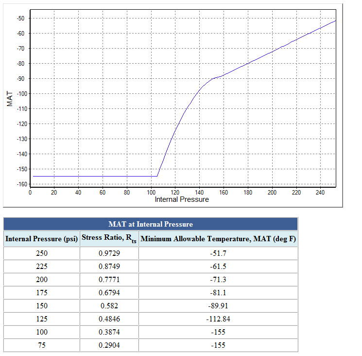
UCS-66 Code rules apply to new construction.  But what if the vessels in your plant were fabricated before 1987, the year the MDMT rules of UCS-66 were put in place?  This is where our API 579-1/ASME FFS-1 Fitness-For-Service software, INSPECT, comes into the picture.  INSPECT includes API 579-1 Part 3 brittle fracture assessments and the ability to produce Minimum Allowable Temperature (MAT) curves . INSPECT’s MAT feature automatically runs Part 3 assessments over a range of pressures to simplify and speed up the creation of equipment integrity operating windows.

Increase Your Capabilities With COMPRESS

Nozzles Simplify the detailing of nozzle attachments with flexible and intuitive nozzle design capabilities. Finite Element Analysis Built-in FEA for Nozzles, Clips and TEMA Expansion Joints. API 650 Storage Tanks Modeling storage tanks is easy as COMPRESS guides you through an intuitive design wizard. Vacuum Rings Drag-and-drop vacuum rings and quickly see how the external pressure rating changes. Quick Design Speed up the process of pressure vessel modeling with Quick Design mode. Productivity Software packages like COMPRESS exist to increase productivity and save Engineering hours. Heat Exchanger Perform ASME UHX and TEMA calculations independently or leverage the bi-directional interface with HTRI. Division II As Division 1 increasingly references Division 2 provisions, many companies are transitioning to Division 2 rules to capitalize on material savings. MDMT Rules of UCS-66 The rules of UCS-66 guard against vessel failure by brittle fracture, a low probability, high consequence event. External Pressure Design Simplify the complexity of the
UG-28 rules for external pressure design and vacuum rating.
Jacketed Vessels Design both conventional and half pipe jacketed vessels. Vessel Wizard The Vessel Wizard speeds pressure vessel design by creating complete pressure vessel models with minimal input. COSTER Import files from COMPRESS and create user customizable pressure vessel cost estimates in spreadsheet format. Flange Design Create optimized Appendix 2 flange designs with minimal time and effort and account for loadings on standard B16.5/16.47 flanges. Weld Seams Designers can visually confirm good practices such as staggered longitudinal seams. Lifting & Rigging Use an accurate weight, the correct center of gravity, and apply the actual section properties. Modeling + Drawings The Codeware Interface includes Drafter 3D, a feature that auto-generates 2D pressure vessel drawings. Related Codes COMPRESS implements a wide range of related engineering methods, codes and standards. Design Mode Save time by reducing the trial and error iterations that would otherwise be required when designing pressure vessels. Rating (Analysis) Mode The COMPRESS Rating Mode takes your design and determines the vessel’s MAWP, MAEP and MDMT. Hydrotest Performing hydrotest stress calculations in the design stage prevents equipment damage during hydrotesting. Hillside Nozzle COMPRESS saves time by calculating chord openings and governing planes of reinforcement automatically. ASME Editions Older ASME Codes are retained in all COMPRESS releases so you can always use the latest software. Automatic Liquid Levels COMPRESS eliminates the need to manually calculate each vessel component’s liquid static head. Global External Loads The Loads Menu allows designers to easily consider global external loads when sizing pressure vessel supports. Clips and Lugs Quickly add in various structural shapes to complete your design. Multi-Chamber Vessels Certain industrial processes require pressure vessels with multiple chambers operating under different design conditions. Appendix 46 Produce more economical Div 1 pressure vessel designs with increased accuracy from the Div 2 design by rule equations. Manufacturer's Data Reports Simplify the creation, submission and management of ASME Manufacturer’s Data Reports and NBIC Repair and Alteration Forms. Support Skirt Openings Specify piping connections to vertical vessels that require additional piping and openings cut out of the support skirt. Branch Connections Reduce pressure vessel welding and material costs by modeling tees in COMPRESS. Foundation Loads Summary Break down the loads for the specified vessel operating conditions including weight, wind, seismic, and vortex shedding. Shipping Saddles COMPRESS provides a shipping saddle option based on the industry standard Zick Analysis. UG-80 and UG-81 COMPRESS automatically provides out-of-roundness tolerances that must be maintained during pressure vessel fabrication. Nameplate Design Every pressure vessel is required by Code to have a nameplate. COMPRESS handles this by including a convenient nameplate option. Fatigue Screening Quickly enter fatigue data to determine if a fatigue assessment is required. WRC 537 Nozzle Loads Check stresses on nozzles using WRC 107 and WRC 537 stress analysis for spherical and cylindrical shells.
COMPRESS Quick Design Mode Heat Exchanger designed in COMPRESS Division 2 option in COMPRESS MDMT Rules of UCS-66 Bill of Materials generated from COSTER Flange design in COMPRESS Weld seam wizard in COMPRESS Lifting mechanics in COMPRESS Drafter 3D from Codeware COMPRESS includes related engineering methods, codes, and standards Design mode in COMPRESS Rating mode in COMPRESS Hydrotesting in COMPRESS Hillside Nozzle design in COMPRESS 2023 ASME VIII Code Edition in COMPRESS Automatic Liquid Levels in COMPRESS External Loads in COMPRESS Pressure Vessel clip with pad in COMPRESS Multi chamber pressure vessels in COMPRESS Appendix 46 in COMPRESS ASME Manufacturer's data reports in COMPRESS Support Skirt Openings in COMPRESS Foundation Loads Summary in COMPRESS UG-80 and UG-81 design in COMPRESS Jacketed Vessel in COMPRESS Pressure vessel nozzles Shipping Saddles in COMPRESS Nameplate design in COMPRESS WRC 537 Nozzle Loads in COMPRESS Fatigue Screening in COMPRESS Vacuum Rings in COMPRESS FEA Nozzles in COMPRESS API 650 in COMPRESS Branch Connections in COMPRESS