Heat Exchanger Drawings

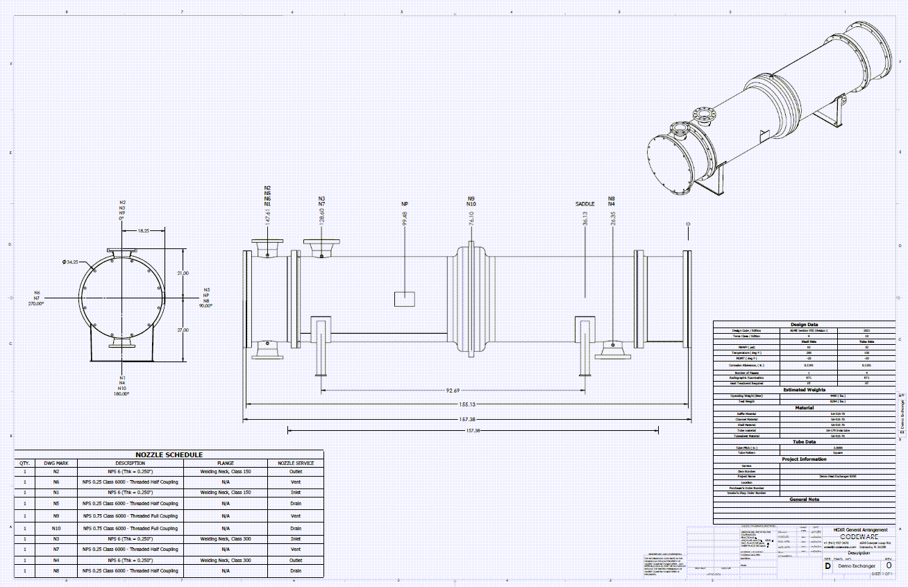
The Codeware Interface (CWI) add-in for Autodesk Inventor streamlines the creation of heat exchanger drawings, making it easy to produce high-quality, standards-compliant documentation. Users can quickly set up and customize Inventor drawing templates to match internal drafting standards, ensuring consistency across projects.

CWI-generated drawings are fully editable and can be updated efficiently as designs evolve, reducing rework and saving time. Tables and schedules can be easily created, modified, and repositioned to suit specific project requirements.

General arrangement drawings are generated automatically, while detailed nozzle drawings include weld information and shop floor WPS numbers. Tubesheet detail drawings also incorporate critical joint information, including UW-20.1 and 11.3-1 tube-to-tubesheet configurations, providing the level of detail required for fabrication and review.

A custom drawing of a Heat Exchanger with nozzles protruding out of an expansion joint created by the Codeware Interface add-in
Heat Exchanger Bundle Drawing created in COMPRESS exported to Inventor

Produce Shell and Tube Heat Exchanger Drawings

The Codeware Interface Add-in also supports advanced smart solid modeling techniques including Assembly Representations in Inventor:

  • Shell roll-outs with nozzle openings, nozzle schedules, nozzle detail drawings, nozzle cut lists, U-tube bend schedules, bills of materials, and more are created faster and with fewer mistakes.
  • Solid models include tube bundle assemblies with tubesheets, baffle plates, tie rods, and spacer tubes.
  • The CWI includes Drafter 3D, a “one push button” feature that automatically produces to-scale drawings.

Featured Heat Exchanger Design Capabilities

Efficient Modeling Simplify heat exchanger design with a guided workflow and built-in ASME and TEMA code compliance. Design Conditions Simplify complex heat exchanger design by allowing multiple operating conditions to be evaluated simultaneously, including true MAWP determination. Tube Bundle Streamline tube bundle replacement by modeling and analyzing only the bundle without recreating the full exchanger. Multiple Codes Supports multiple ASME and TEMA code editions, automatically applying the correct allowable stress values for each. Flange Design Automate complex flange analysis by accounting for shared bolting, governing loads, and iterating conditions to determine accurate MAWP. FEA for Expansion Joints Integrated FEA for TEMA expansion joints, enabling fast, automated analysis with minimal setup and optimized performance. Lift Lugs for Channels Enable lift lug design directly on exchanger subassemblies, eliminating the need to recreate components in separate files. ASME Reports Generate comprehensive, easy-to-navigate ASME calculation reports covering all design and hydrotest conditions. ASME PCC-1 Appendix O Evaluate bolted joints per PCC-1 Appendix O, determining optimal bolt stress and torque while ensuring gasket, bolt, and flange integrity. Automated Drawings The Codeware Interface is an Autodesk Inventor add-in that generates drawings and solid models from COMPRESS designs Finite Element Analysis in COMPRESS