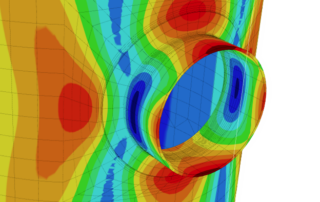
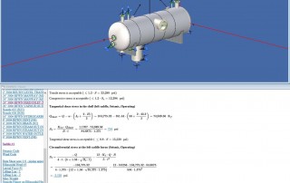
Finite Element Analysis (FEA) in COMPRESS
COMPRESS includes nozzle FEA for cases where a more accurate solution is required. The COMPRESS FEA engine was created by Codeware to address the detailed requirements of ASME Code stress analysis. It features [...]
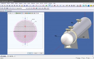
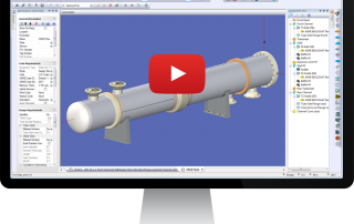
Heat Exchanger Mechanical Design in COMPRESS
Integrated Heat Exchanger Design and Fabrication Using COMPRESS Are you looking to expand your business by taking on heat exchanger work? COMPRESS offers a Heat Exchanger add-on to help expand your capabilities by: Interfacing with Codeware's [...]
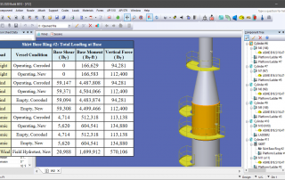
Foundation Loads Summary, UG-80 and UG-81 in COMPRESS
July 6, 2020 - We're pleased to announce the release of COMPRESS 2020 Build 8010. Productivity enhancing new features include: UG-80 and UG-81 Out-of-Roundness Forming Tolerances Foundation Loads Summary Attaching ASME B16.9 [...]
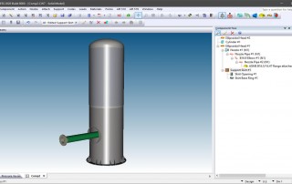
Support Skirt Openings And Nozzle Extensions
Vertical pressure vessels usually need a support skirt opening to allow attachment to process piping. COMPRESS saves hours by efficiently modeling these skirt openings and additional piping components. This short video shows how COMPRESS [...]
Advanced ASME Reports, Code Compliance, and Maintaining Nozzle Positions in COMPRESS
We're pleased to announce the release of COMPRESS 2020 Build 8000. New features include: Compliance with the 2019 Edition of the ASME Code Advanced Report Formatting for easier to read design reports [...]
Nozzle Couplings and Slotted Anchor Bolt Holes in COMPRESS
We're pleased to announce the release of COMPRESS 2019 Build 7910. New features include: Additional nozzle coupling types An improved heat exchanger entry dialog Slotted saddle anchor bolt holes [...]
+1 (941) 927-2670 | sales@codeware.com