Create Drawings Automatically With The Codeware Interface®
The Codeware Interface (CWI) saves time and reduces errors by quickly generating SOLIDWORKS® or Inventor® pressure vessel solid models and drawings from COMPRESS and INSPECT designs. The CWI is an add-in for SOLIDWORKS or Inventor and is supplied at no extra cost to Codeware clients. It manages the data associated with the imported design files through the use of iProperties (Inventor) or Custom Properties (SOLIDWORKS).
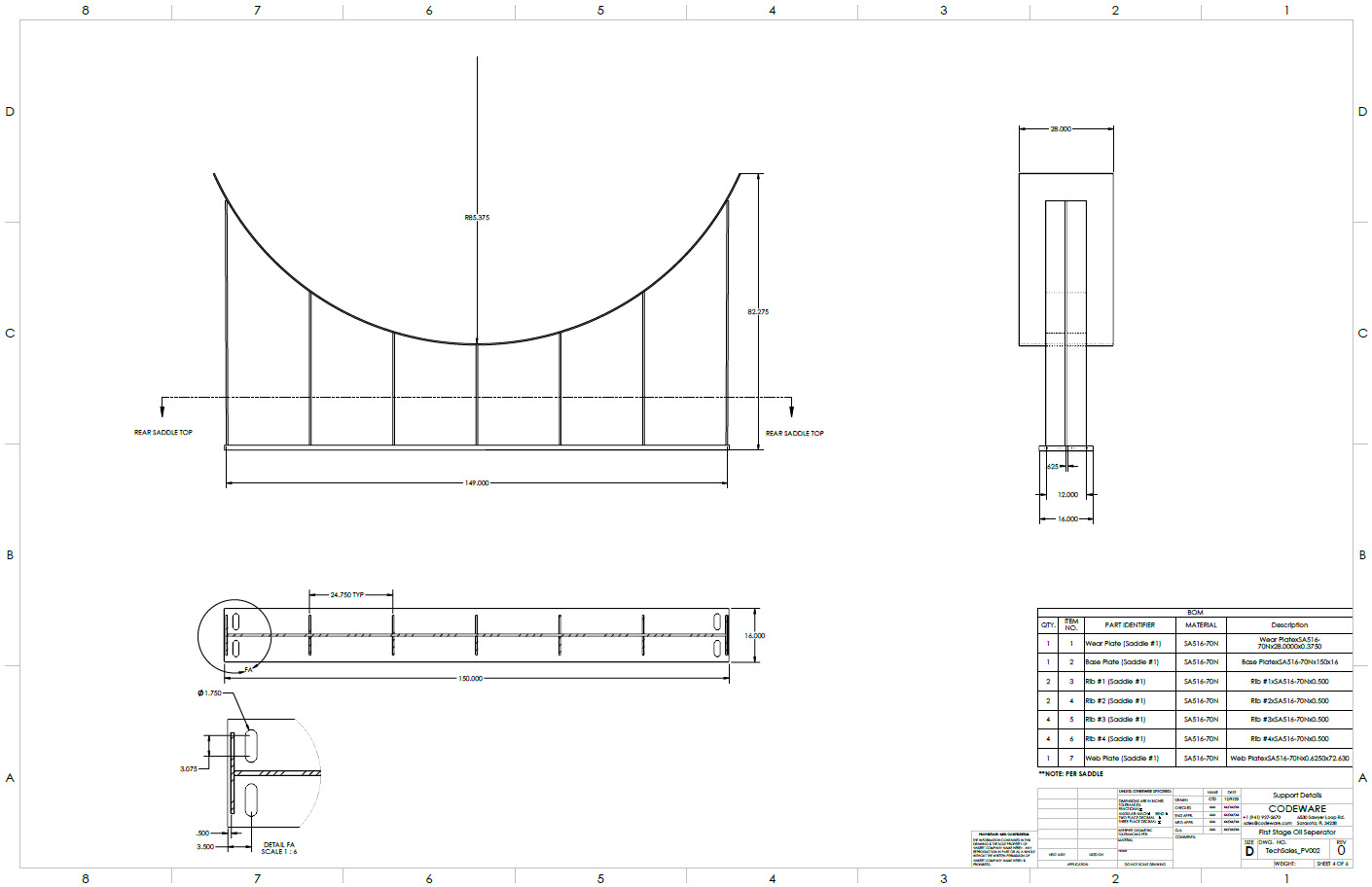
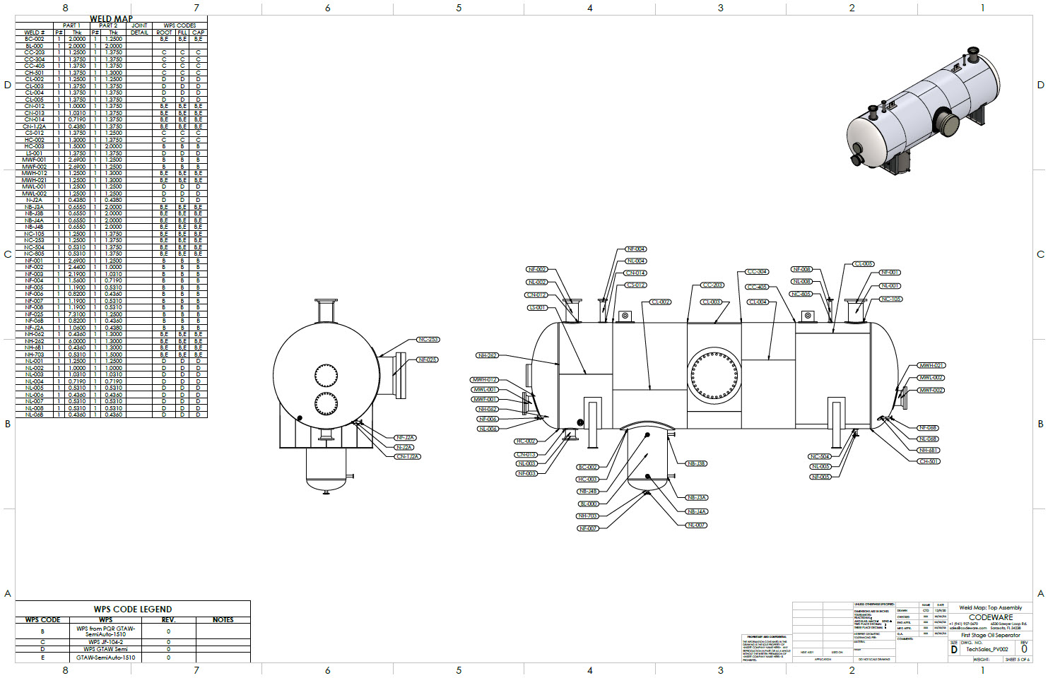
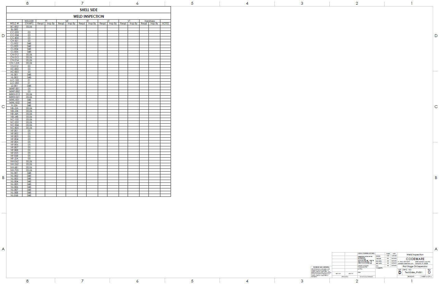
Detailed Pressure Vessel Drawings
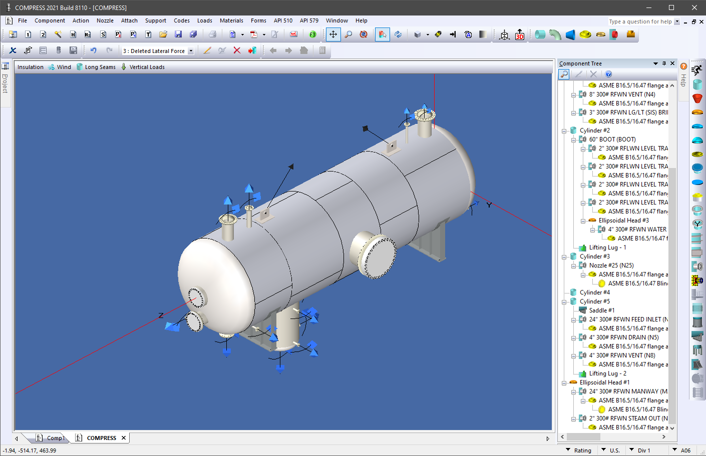
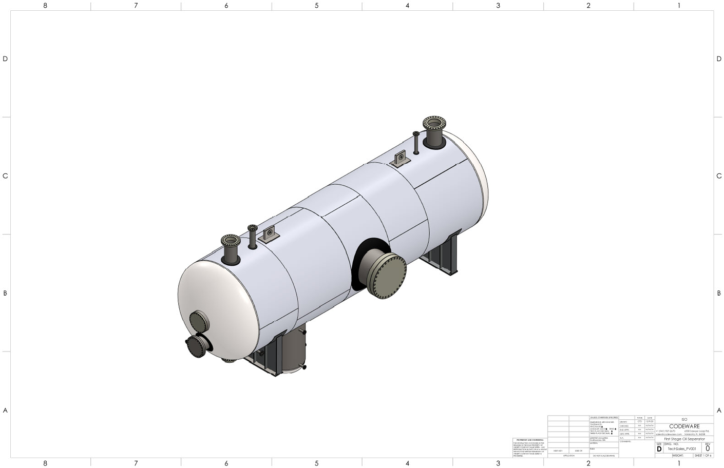
Automated Drawing from Exported COMPRESS Model
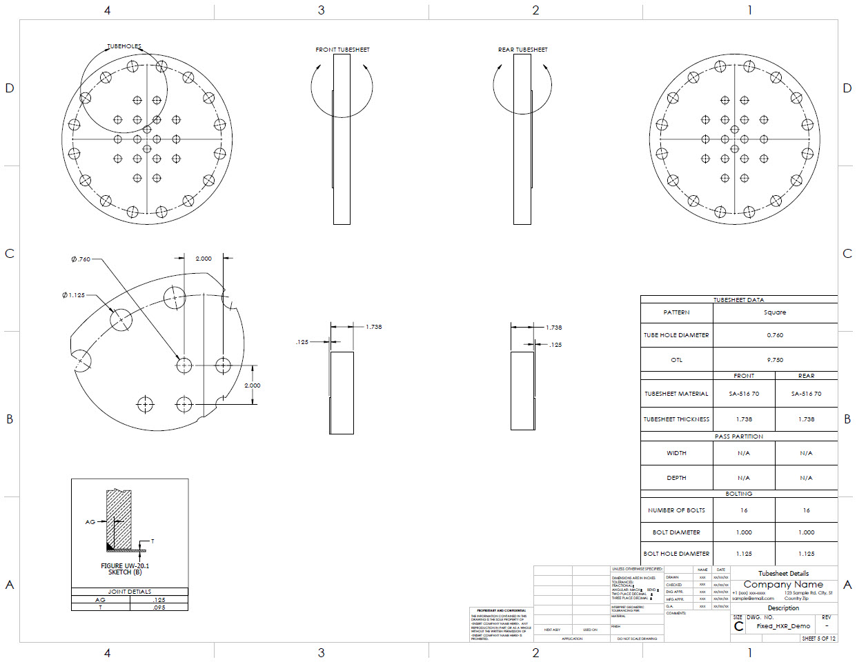
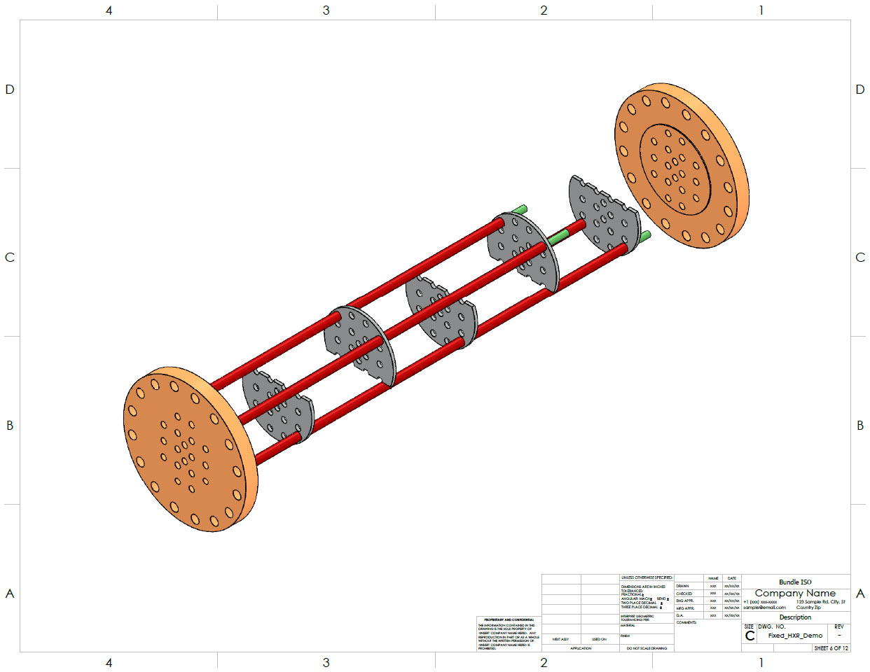
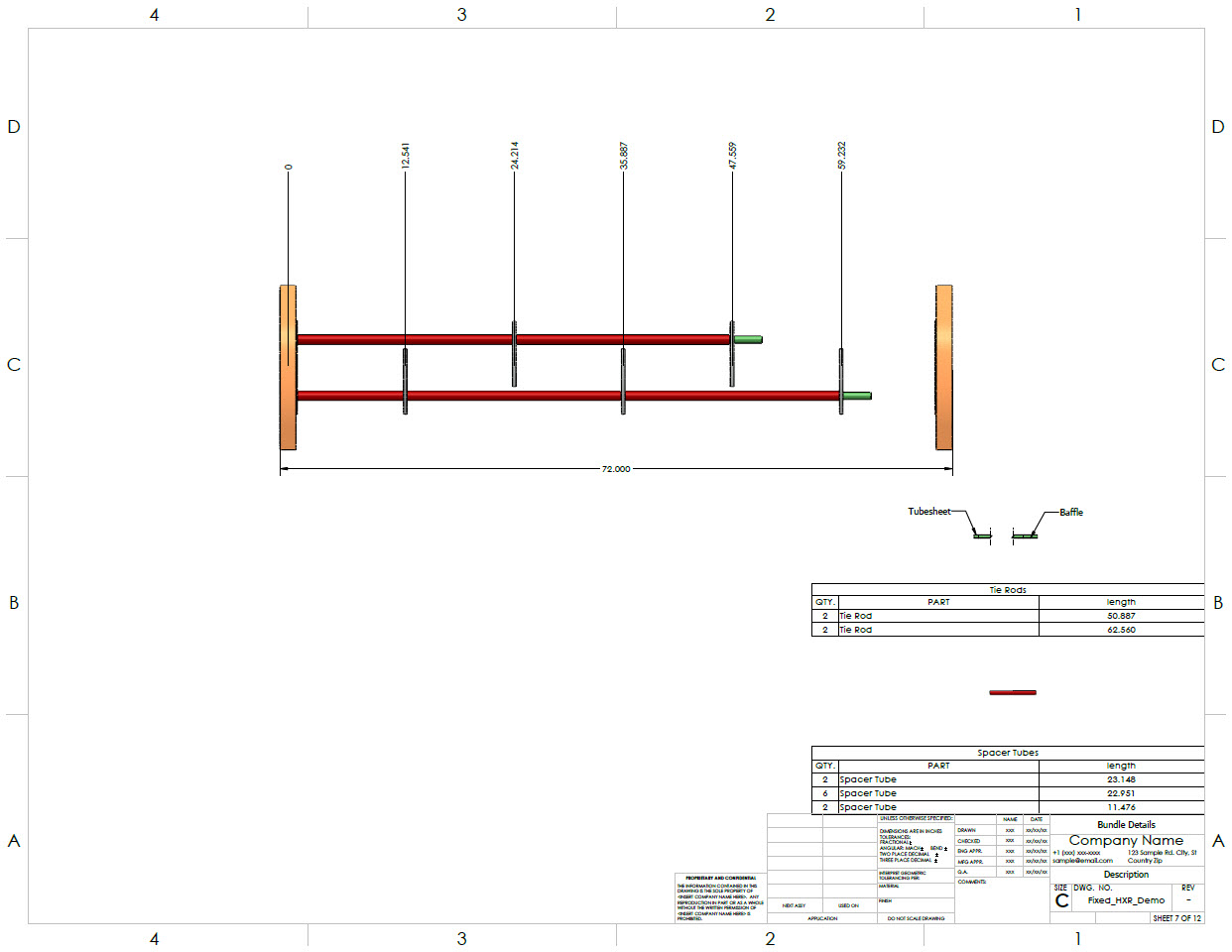
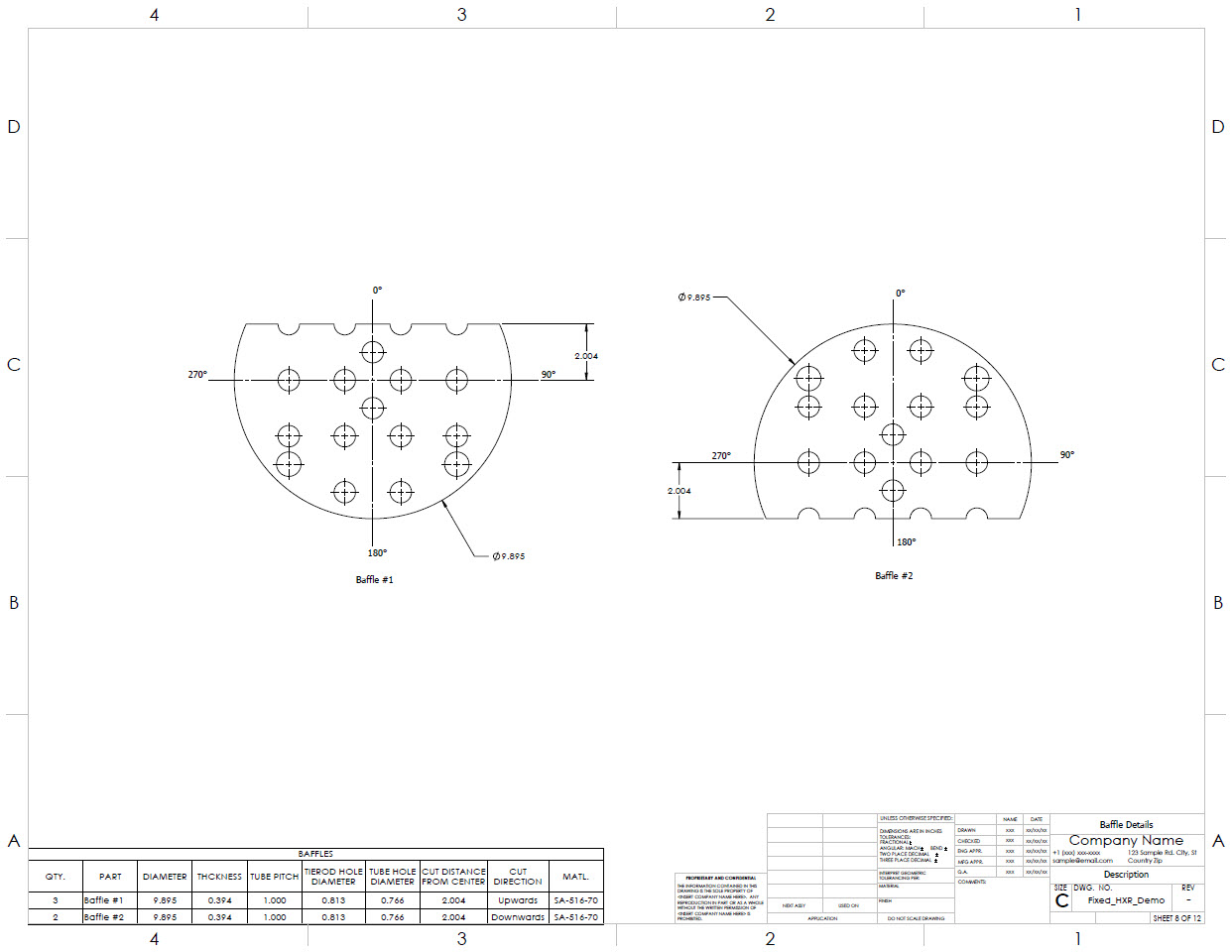
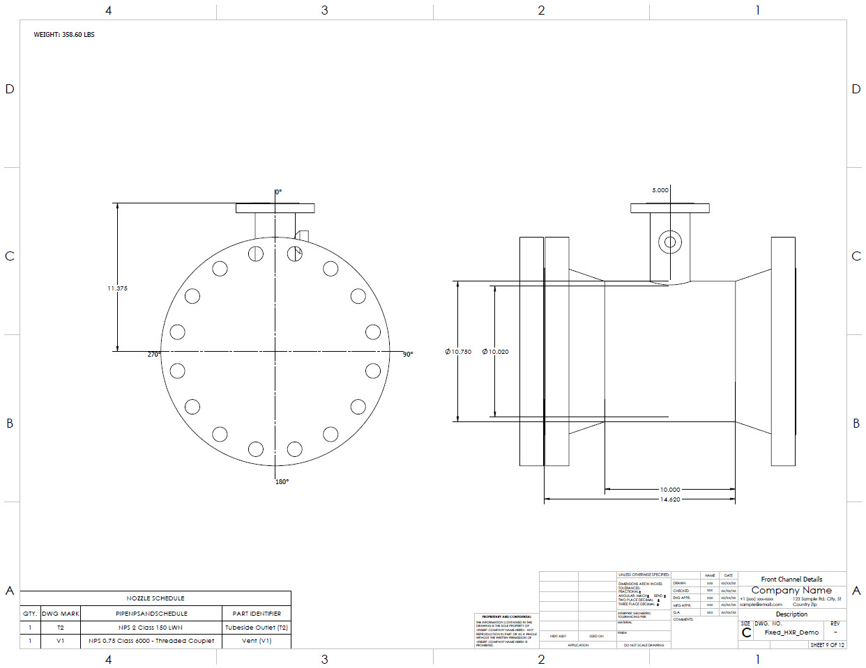
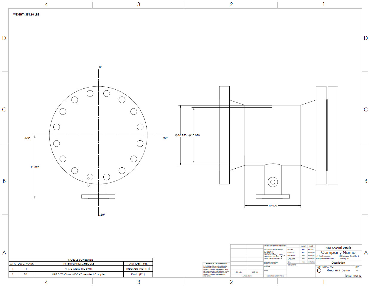
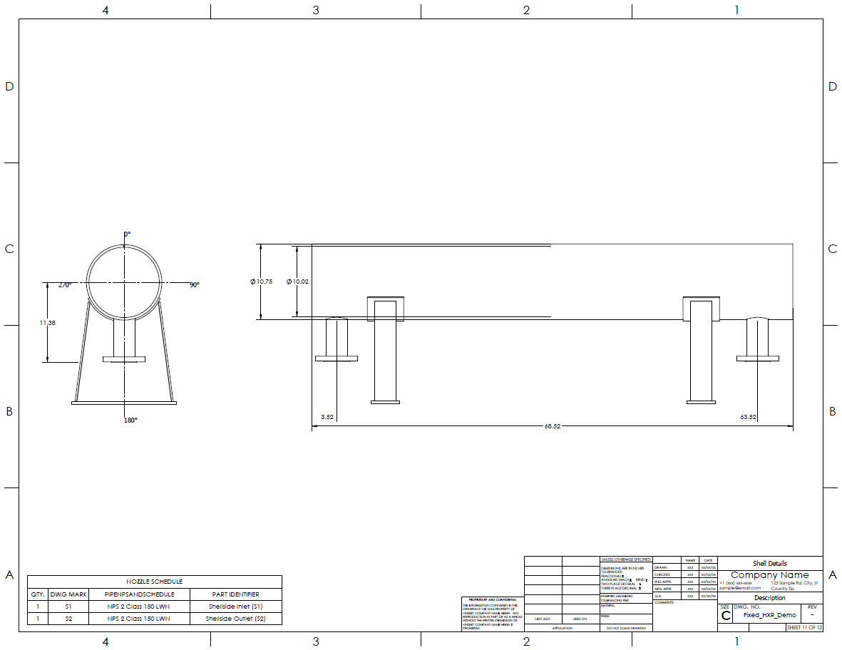
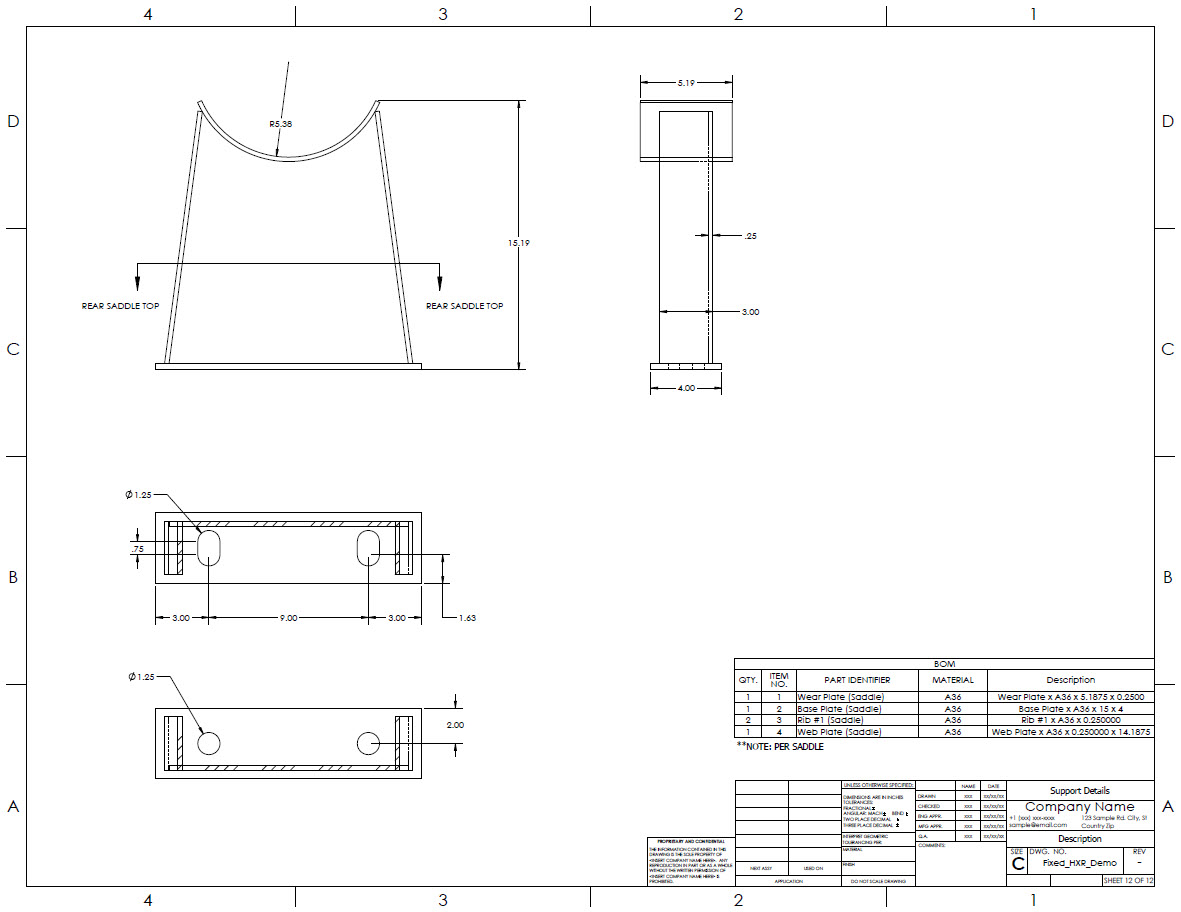
Detailed Heat Exchanger Drawings
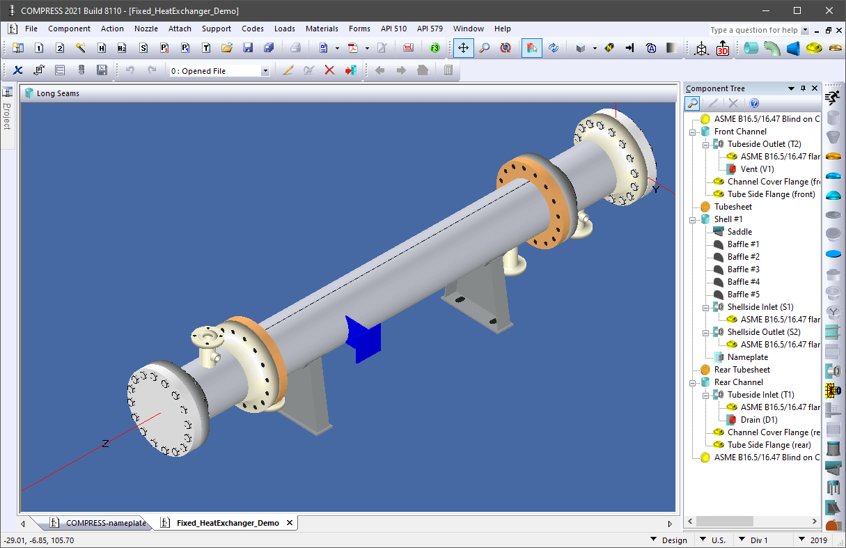
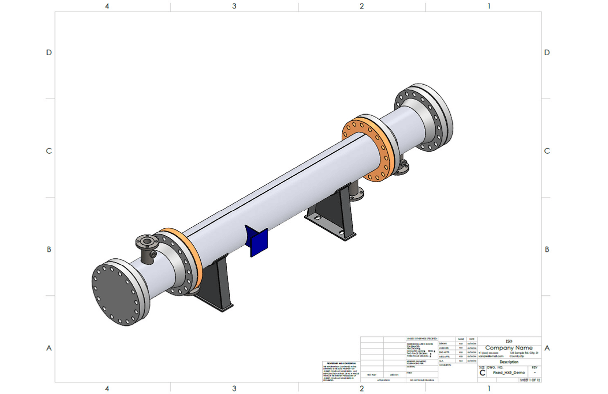
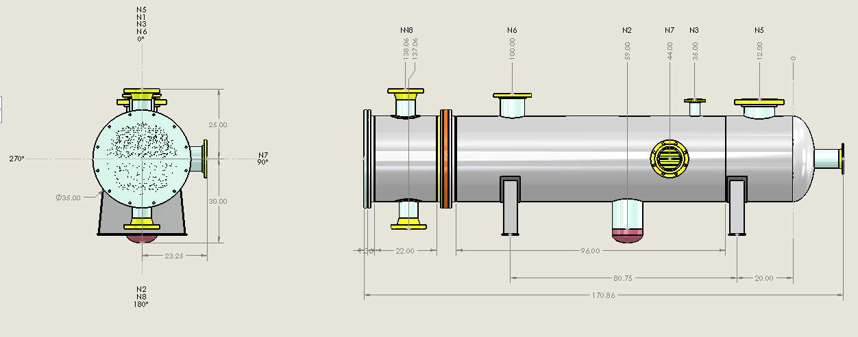
Automated Drawing from Exported Heat Exchanger Model Designed in COMPRESS
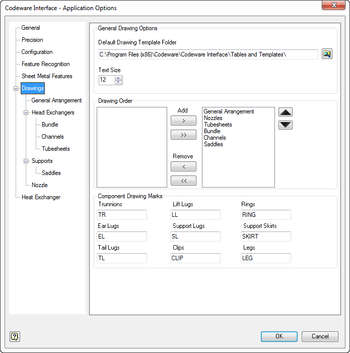
Codeware Interface Drawing Options
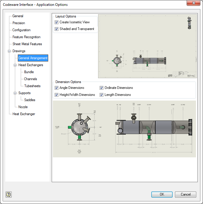
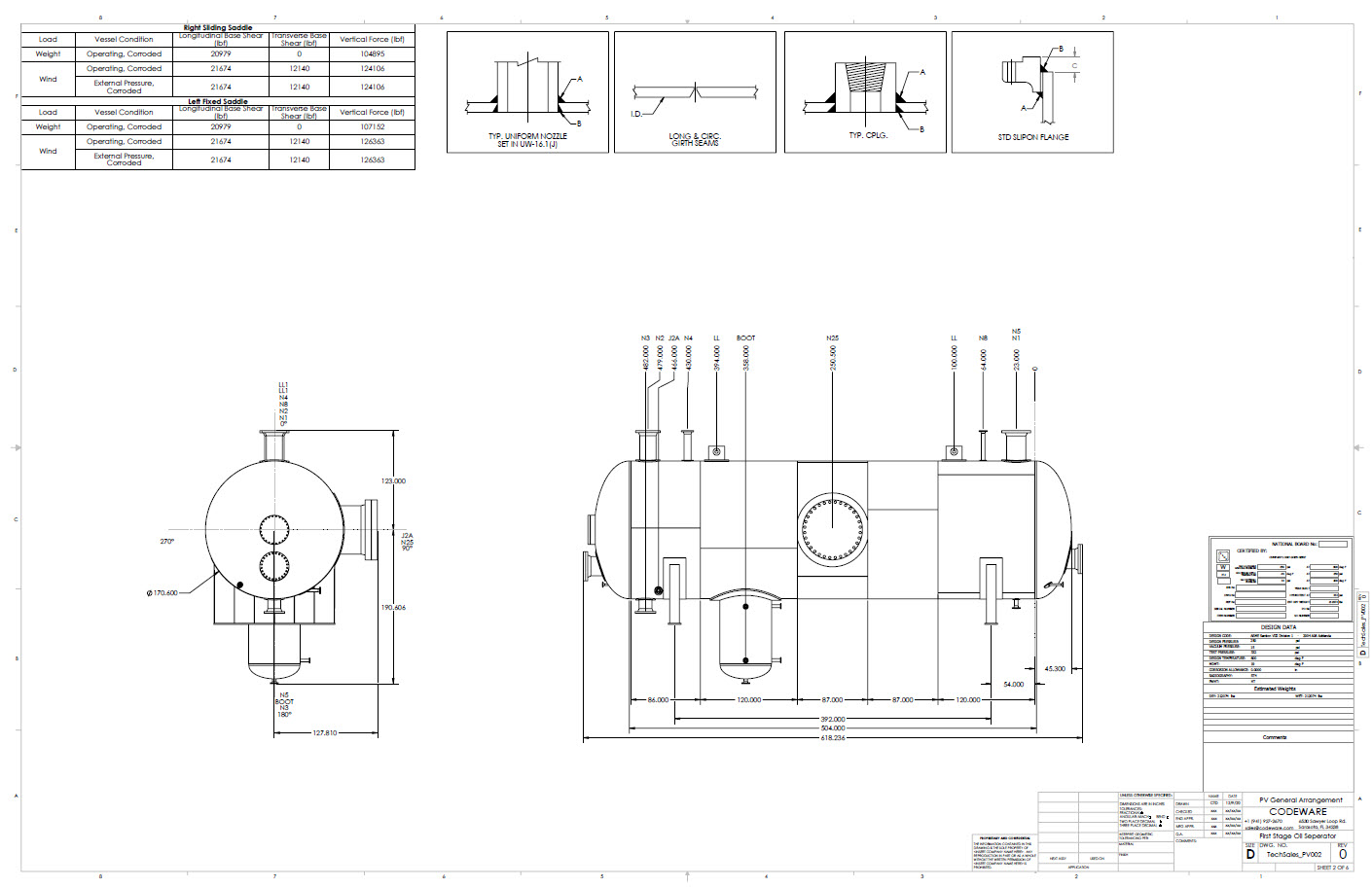
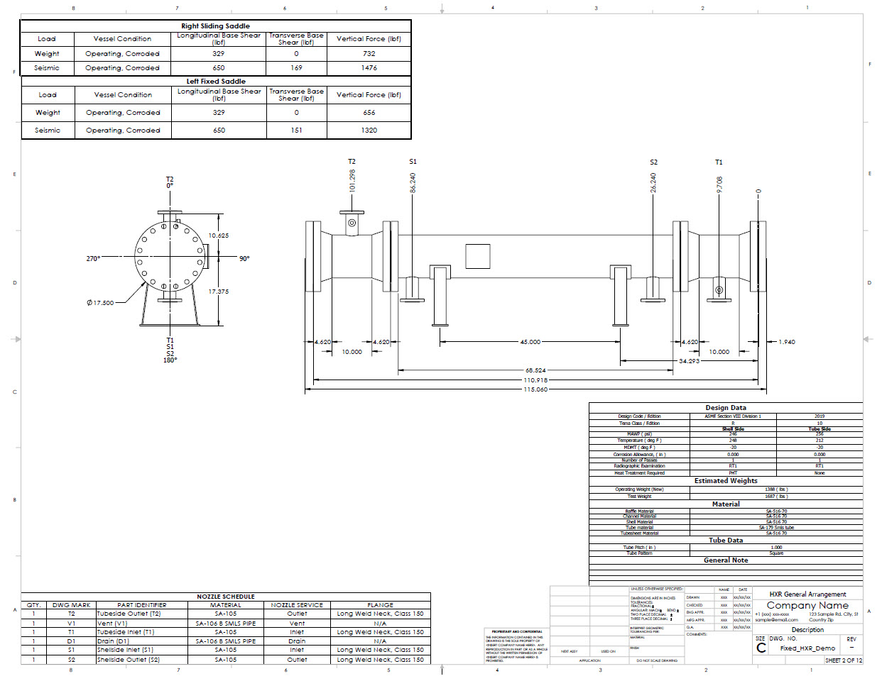
Efficiently create and customize front, side and isometric views of your vessels. The front and side views include attachment angle, ordinate, length along with height/width dimensions.
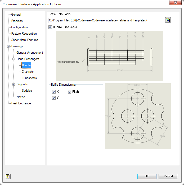
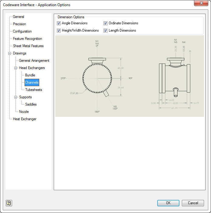
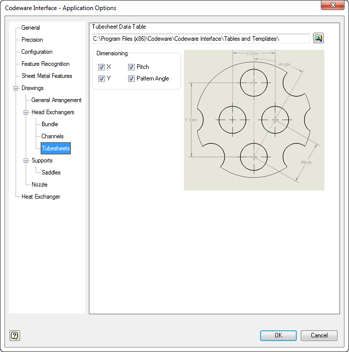
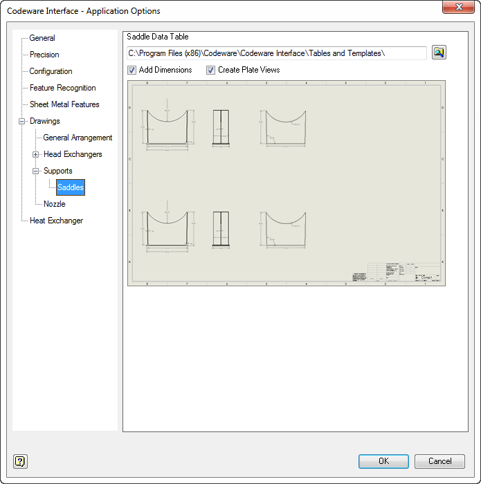
Customizable heat exchanger drawings include bundle, channels and tubesheets. Applicable height, width, thickness and tube layout dimensions are available for automatic application.
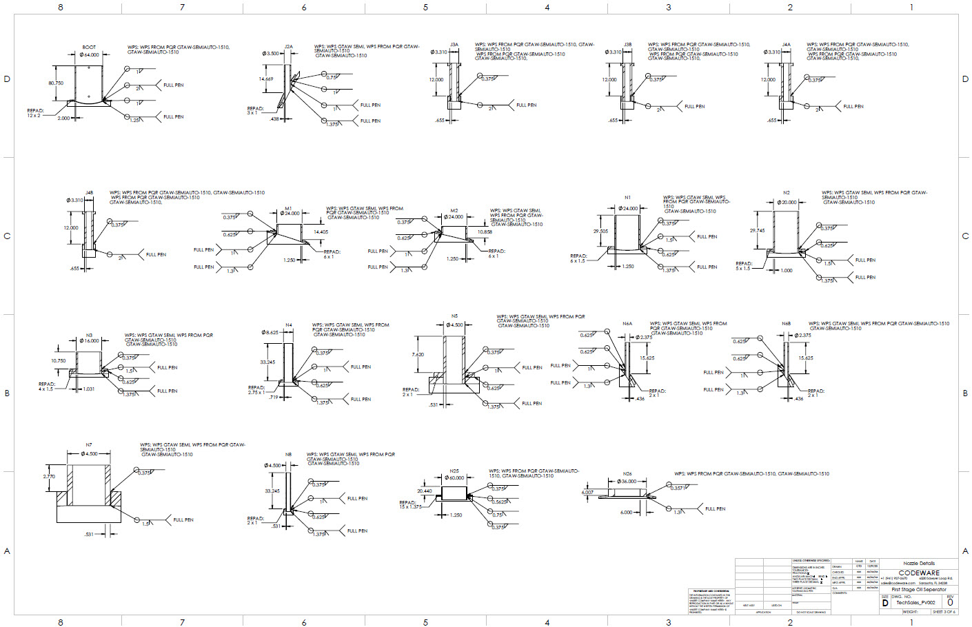
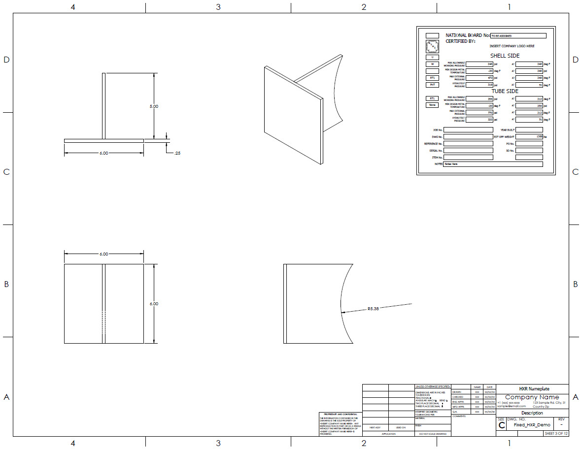
Custom flange detail drawings automatically include the component identifier and dimensions.
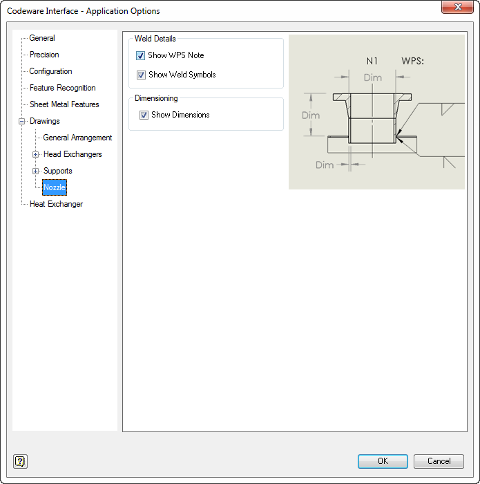
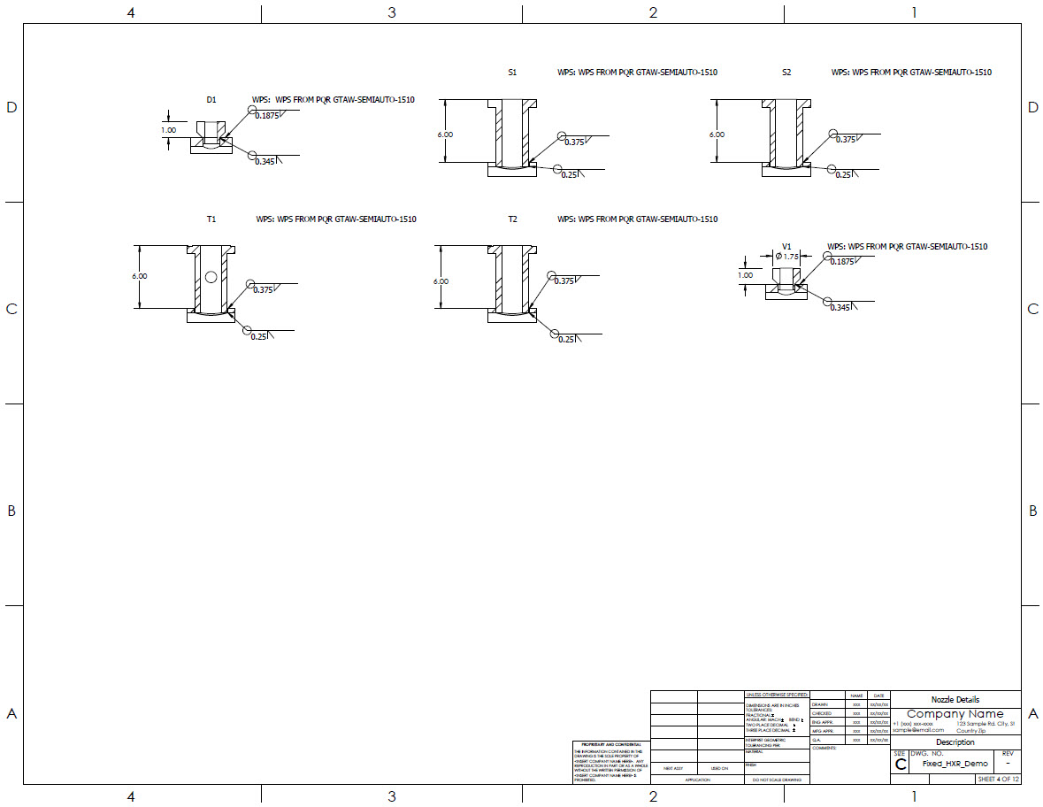
Nozzle drawings automatically include details such as weld symbols and dimensions. When used in combination with Shopfloor, WPS numbers and notes are shown.