API 579 Part 4 and Part 5 – General and Local Metal Loss
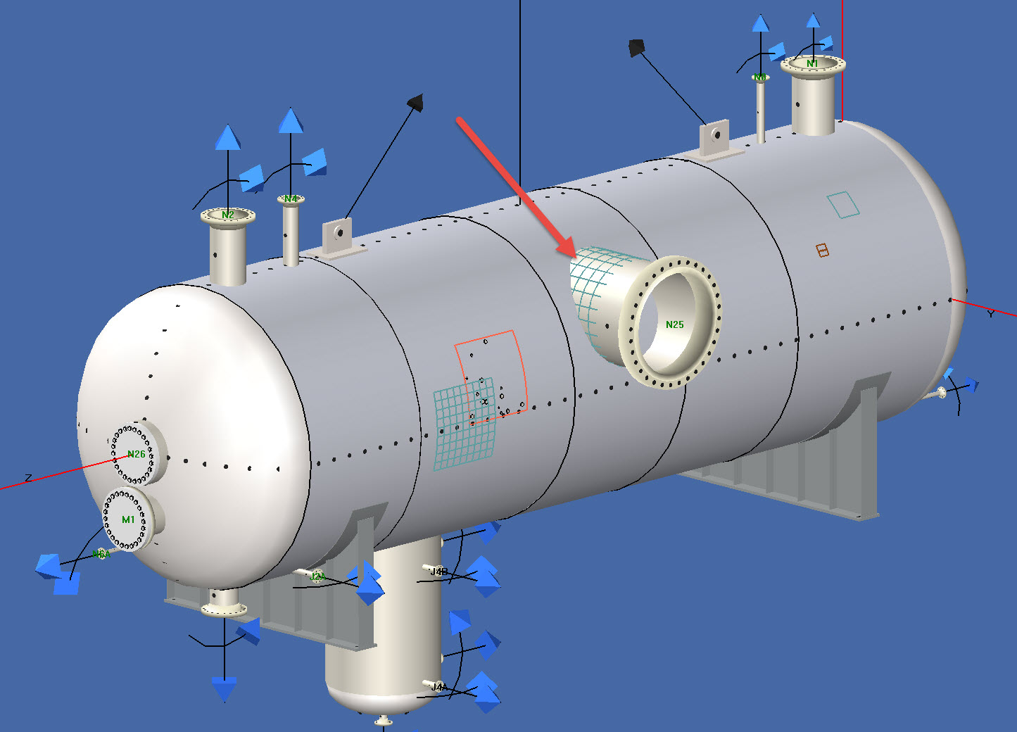
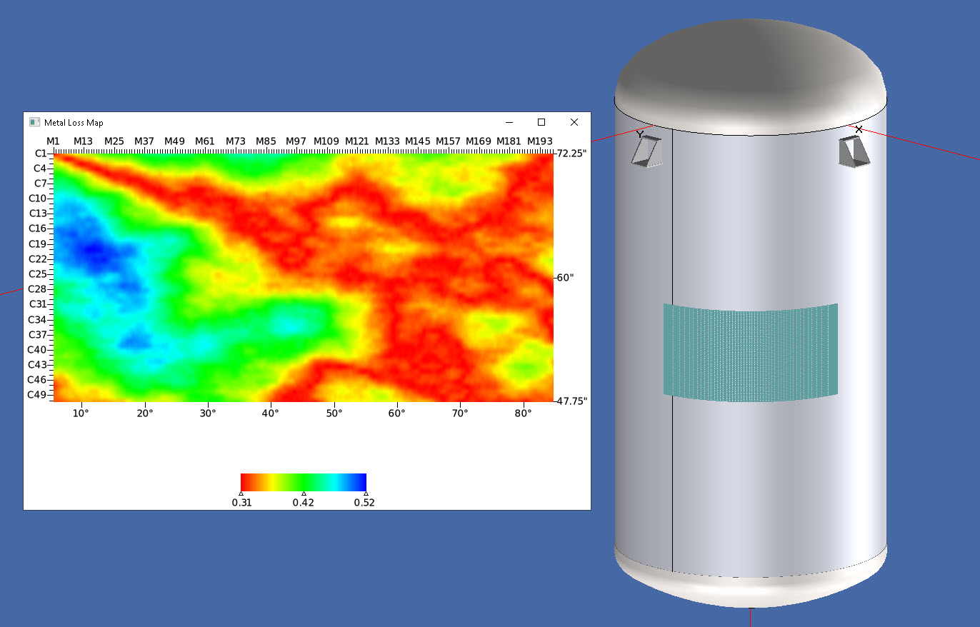
Metal loss is one of the most common flaws encountered in service. INSPECT addresses metal loss with its rigorous API 579-1 general and local metal loss assessments and detailed reports. INSPECT’s 3D models take the guess work out of verifying that the metal loss has been correctly entered. Since other flaws such as pitting are often present within metal loss regions, INSPECT detects pitting overlaid onto the metal loss and factors this in accordingly. INSPECT covers:
Part 5 – Groove-like Flaws
API 579 Part 5 groove-like flaw assessments can be utilized in INSPECT to perform “What if” scenarios for possible remedies to flawed areas. For example, would the flaw pass assessment if the crack or metal loss was ground into a groove-like flaw? Groove-like flaws may be combined with pitting damage (Part 6) as well.
Create Detailed Part 4 and Part 5 Reports
INSPECT quickly generates metal loss assessment reports. INSPECT reports contain a full audit trail of all API 579 calculations performed including equations and tables referenced. Other engineering highlights include:
How to Perform Part 5 Local Metal Loss Assessments in INSPECT
More Information on Metal Loss Can be Found at:
FFS Forum: Thickness Grids & Critical Thickness Profiles by Inspectioneering
FFS Forum: Corrosion Assessment without the Grid by Inspectioneering


 curve in INSPECT")


 with INSPECT")


+1 (941) 927-2670 | sales@codeware.com