The Advantages of Locating Pressure Vessel Weld Seams

Although not required to perform basic (theoretical) ASME calculations, specifying weld seam locations when designing pressure vessels provides a number of practical advantages:

  • Tall towers often require greater thicknesses near the bottom to resist wind and seismic loadings. Locating circumferential shell seams is necessary to correctly calculate this arrangement.

  • It is good practice to avoid placing certain vessel components through or over weld seams if possible.  Entering the actual weld locations means nozzles passing through weld seams, reinforcing pads and vacuum rings covering weld seams, etc.  are obvious on the 3D\solid model display.

  • Designers can visually confirm other good practices such as staggered longitudinal seams.

  • Cost estimates produced by COSTER are more accurate.

  • Shop fabrication drawings created by the Codeware Interface (Drafter 3D) are correctly detailed.

  • Proper weld procedures and welder assignments can be made by Shopfloor.

  • API-510 (tmin)  calculations made by INSPECT can use the proper local joint efficiency at each CML to extend vessel life and inspection intervals.

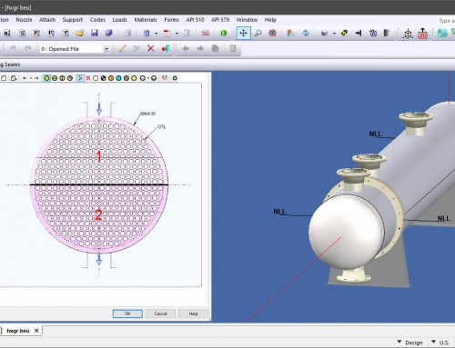
The COMPRESS\INSPECT shell seams feature also creates a shell roll-out sketch that is included in the seams report.

Shell seams are turned on by default for all new pressure vessels created in COMPRESS Build 6310 and later.  To view seams on a design created in an earlier Build:

  1. Open the file in the most recent version of COMPRESS or INSPECT.
  2. Select Action > Set Mode Options > Defaults > Long Seams.
  3. Check “Show longitudinal seams on cylinders, transitions, skirts, and hemi heads”.

Pressure vessel weld seams is just one of the many features enjoyed by users of our suite of software products. To find out more email sales@codeware.com or call us at (941) 927-2670 and set up a software demonstration today.

Having trouble viewing this video?