Clients often ask us “why should my company adopt solid modeling?” and “what are the advantages over my current method?”. In this article I hope to shed some light on these questions and also provide my overall impression of where I think the industry is going and why. In my experience, solid models help in the following areas:
- Plant Layout – Equipment “knows” its weight and attachment point locations
- FEA and CFD – Open the door to further analysis
- Fabrication Drawings – Turn 3D into 2D
I’ve noticed that not all solid models are created equal. Before getting into the details, let’s get on the same page about what a solid model should be. Figure 1 shows a vessel modeled in COMPRESS and Figure 2 illustrates its Autodesk Inventor counterpart. This model was exported directly from COMPRESS to Inventor via the Codeware Interface.

Figure 1 – Pressure Vessel Solid Model in COMPRESS

Figure 2 – COMPRESS Solid Model Exported to Inventor
It is obvious that both programs show a high level of geometric detail. This is very useful for visually verifying that the equipment has been modeled correctly. But what about the non-geometric detail? What about details such as material specification, radiographic examination and service?
One of the biggest, and most confusing, terms you will hear these days is the term “smart model”. It seems that everybody has a “smart” model. But what is a smart model? We define it as a model that contains all the engineering knowledge necessary to fabricate, install and maintain the equipment throughout its lifecycle. It contains “sketches” and “features” that permit SM programs like Inventor to access the information to create components, tables and drawings. The model shown above includes this and companion ASME Code details calculated by COMPRESS such as MAWP, MAP, MAEP, MDMT, required thicknesses etc. This is what I think of when I hear the term “smart model”. Personally, I wish people would just use the term “solid model” and omit “smart” as it’s reasonable to expect a solid model to contain all the information mentioned above.
Now that you know what data a good solid model should contain, I want to go over how having this information available within SM programs improves efficiency.
Plant Layout
Equipment “knows” its weight and attachment point locations
Plant layout has become a hot topic these days. It seems that many companies are trying to break into this space and provide the latest and greatest plant layout technology. From what I have seen, much of our industry seems to be stuck using 1980’s era technology.
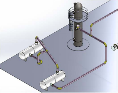
Autodesk is making progress in this area by offering an AutoCAD Plant 3D program. Figure 3 shows a simple layout I made in Inventor using the models exported from COMPRESS. Because the equipment solid models can “talk” to the plant layout SM I was able to quickly connect and route the process piping using the built-in Inventor tools. Similarly, the solid model “knows” how much it weighs (which is required when designing the supporting steel work and foundations). Vessels and exchangers used by the process industry are highly engineered custom pieces of equipment that must meet the ASME Section VIII Safety Code. Simply entering “placeholder” solid models, ones that may look okay from the outside, practically ensures that bad information will find its way into the design process.
So, instead of attempting to re-create equipment later on, why don’t we just get the solid model right from the fabricators? Why don’t the owner/operators out there simply send their models back to the fabricators for replacement? See where I am going with this?
Plant Layout
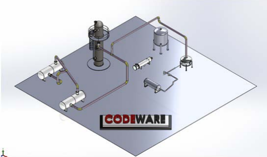
Figure 3 – COMPRESS Pressure Vessel Solid Models Exported to Inventor
FEA and CFD
Open the door to further analysis
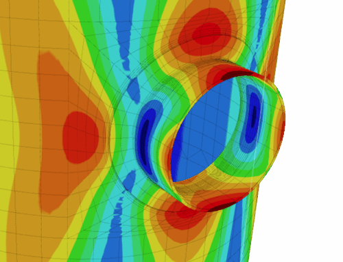
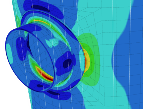
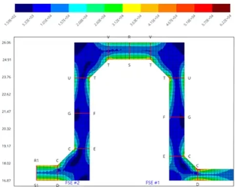
We have all heard of finite element analysis or “FEA” at one point and may have even ventured into this field. Traditionally, it has provided a means of analysis for complex geometries that simply cannot be handled by conventional means. One example is determining the dynamic response of a structure. What if you have vessel components that are outside the scope of the standard ASME VIII design rules? Or perhaps you need to use the design by analysis provisions of ASME VIII-2. In such cases FEA practitioners need to create a solid model geometry for analysis.
Computational fluid dynamics or “CFD” can be used to calculate thermal performance and pressure drops for shell and tube heat exchangers. These simulations can reduce or eliminate the need to build prototypes and can speed up the design process.
In both FEA and CFD the first step is to create the solid model geometry, a task handled quickly and easily by COMPRESS.
Fabrication Drawings
Turn 3D into 2D
Probably the biggest concern I hear now-a-days is “how can we speed up our drafting department?”. Drafters are always under pressure to deliver top quality detailed drawings. So, how can we speed up drawing production without sacrificing quality and potentially introducing burn out in the drafting department? You guessed it, why not use the solid model?
I mentioned earlier that I would touch on using the data in the model. Below is a quick way to show this using some of the tools built into SM software like Inventor. I simply took the solid model and dragged it into a blank drawing template. By utilizing blocks and tables I could quickly pull information over to a name plate and design data table.

Figure 4 – Solid Model Data Populates Tables Automatically
I am not limited in what I can do either. What if I wanted to make a nozzle schedule? How about a nozzle cut list? How about a U-tube bend schedule? Well, I can utilize custom tables to call out any information stored in the model.

Solid Model Properties
The properties you see in the above table were taken directly from the model. They can also be rearranged, added to, or changed. For example, you can edit the table and place any of the custom properties on the table and then re-save it.
What this allows is for drafting departments to set their own company standards without getting that “One size fits all” feel you used to get with generic drawing programs.

Custom Properties
Conclusion
There is a general shift in the industry to move into this new world of solid modeling. It kind of reminds me of hearing my mentors talk about the time drafters were moving from the drawing boards to AutoCAD or from hand calculations to computer programs. I’m sure that neither of these were overnight switches either but I do think 3D is here to stay and, with that, I hope I shed enough light on this topic so you can see some of the benefits of using it.

+1 (941) 927-2670 | sales@codeware.com